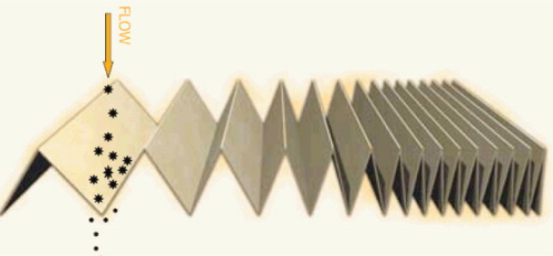

Sieve/barrier or interception type of filtration, whether it is 5 micron absolute filter or a 200 mesh screen, all work primarily by doing little but sieving contaminants. Particles smaller than the pores (voids) in the filtration medium pass straight through and of course, the pores cannot be small enough, as they interrupt and restrict fluid flow too much. Engineers rely on standard Beta Ratios and ISO Tests when specifying conventional filters, which have been continuously developed and redeveloped over the years to meet these same standards (test parameters). But the tests are not truly representative of the real life environment in which these filters are applied.
Within the laboratory environment, filter ISO testing is typically based on a percentage of contaminants captured under a steady state (constant) flow rate. The contaminant introduced is a standard dust as defined within the ISO standard (sand). This cannot, of course, represent the real life characteristics in hydraulic and fluid power systems because it assumes that no valves, actuators, variable volume pumps or external loads are ever imparted on the hydraulic system. Any end-user or designer of fluid power equipment knows that a real-life hydraulic system is anything but constant flow. Dynamic filer efficiency tests undertaken by North Carolina-based Scientific Services showed conventional filtration efficiency as low as 18 percent under varying pressure and peak flow.This is equivalent to a conventional element emitting large and concentrated clouds of contaminant downstream of the filter and headlong into the valves, cylinders and pumps.
Yet hydraulic engineers and customers remain puzzled as to why seemingly clean (as far as the ISO rating goes) pieces of equipment fail to perform or fail on the jobsite without any apparent change in conditions. Clearly the real problem is getting past our conventional filters.
The real threat – microscopic ferrous contamination
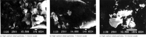
Eighty to ninety percent of products manufactured worldwide are produced from carbon steel. During start-up and break-in, some of the components that are breaking in and being ‘worn in’ will be steel on steel. A large portion of steel (ferrous) contaminant becomes suspended in fluids during this period. This is the reason fluid systems, from the engine and transmission in an automobile to the hydraulic system of an ‘off highway’ piece of mobile equipment, have their oil and filter changed as part of the break-in procedure.But wear continues, and these ferrous contaminants are going to be present throughout the life cycle of any fluid power system, where they catalyse a chain reaction of wear - a few particles circulating in the system and generating additional particles and these additional particles along with the original particles generating even more particles at an exponential rate.These ferrous particles (see Figure 3) have been torn from a hard surface and are the smallest, hardest and sharpest contaminants in fluid systems. Few engineers would disagree that the mere suggestion of their presence in a fluid power system presents a major issue in terms of system design and reliability. Yet still many do not prioritise on identifying an effective and efficient technology to address the situation because these ferrous particles are typically under 15 microns in size and most are in the 5-10 micron range. Most conventional filter elements used today are 10 microns.Every engineer would like to use a 1 micron absolute rated filter element in their system, if only the solution did not involve so much cost, complexity and turn out to be so physically big to overcome the limitations of maximum allowable pressure drop across a filter element to maintain flow rates.This leaves almost every piece of high carbon steel under or near 10 microns in size to freely circulate around the system. Conventional filtration needs a bit of extra help.
Past attempts to deal with the risk
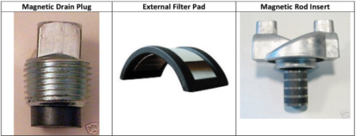
Most sophisticated hydraulic systems, aircraft and aviation hydraulics, already use some form of magnetic filter. The fact that these products even exist serves to demonstrate that the problem has been known for many years. That they can actually increase the risks is not commonly understood.
The main problem with these early attempts is one of simple physics, namely that magnetic energy drops off in strength by the inverse of the cube, over distance. In other words, contaminant has to be very close to the magnetic source to be attracted. Even worse, as contaminants build-up on the magnetic surface, these devices cannot hold on to them and they simply wash off back into the system. But they do not simply drop back into suspension within the hydraulic fluid. Since the particles have been exposed to a magnetic field, they generally remain as a clump, weakly magnetised together. This is why sudden catastrophic failures of single components occur in systems that appear to be in perfect condition previously. Engineers are left confused until they inspect the failed component and typically find high carbon steel contaminant embedded in the softer wear metals close to where the fluid is introduced to the component.
The magnetic solution that works
A solution lies in the magnetic core technology, designed and patented in the U.K. by Magnom Corp., which now has products installed worldwide in applications ranging from domestic heating systems to commercial wind turbines and off-road construction plant. Magnom’s core technology was originally developed in partnership with the Formula 1 racing industry. Ideas were honed and tested on the race track in some of the most gruelling and performance demanding environments.
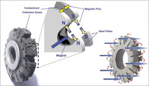
The result is a very simple, yet effective filtration solution. The basic form of the technology consists of a permanent power source provided by a magnet that is sandwiched between two carbon steel plates (See Figure 5).
The steel plates intensify the magnetic flux field as steel transmits magnetic flux up to 15 times more efficiently than the magnet itself. This is the underlying principal of why laminations of steel are used in armatures of generators and motors. They also project and focus this increase in energy directly into the fluid flow and provide a very secure trap to hold contaminant out of the fluid flow. These traps prevent captured contaminant from being washed back into the hydraulic system.
The fluid flow channels are cut directly out of the steel to ensure that the total cross sectional area of the fluid flow channels exceeds the cross sectional flow area of any feed pipe or hose delivering fluid to the core by up to 15 percent. This means that the cores deliver a minimal pressure drop even if full of contaminant. This means they can be located anywhere in the hydraulic system and in a full fluid flow capacity, before a sensitive variable displacement pump for instance.
In real life fluid power situations, core units have been observed to remove particles as small as 0.07 microns in size and to remove up to 97 percent of the particles in a single pass through the core. In other configurations and situations cores can approach closer to 100 percent efficiency on a single pass through the filter.
The bottom line
By isolating and removing the most damaging contaminant to a fluid power system, the magnetic core technology delivers dramatic improvements in the reliability and performance of systems which translates into:
• lower maintenance and warranty costs;
• longer hydraulic and lubricating fluid life;
• extended conventional filter life;
• longer equipment service life; and
• increased equipment availability.


