Introduction
Several applications for Automatic Particle Counters (APC) require the sensor to be directly linked to the fluid line. This is the case in drinking water treatment facilities. Continuous monitoring of sand filter performance is ensured by light extinction sensors set to count micron size particles and online counting is required for a number of reasons:
• Economy: filters operate 24 hours a day and 365 days a year and manual sampling results in unacceptable costs.
• Permanent quality insurance: water has to fulfil drinkability requirements continuously when distributed to networks, and online monitoring is the only acceptable means for detecting any instantaneous operational problems or dysfunctionality.
• Reliability of results: providing sensors and counters are correctly installed and calibrated, a constant flow of water directly sampled from the filtrate pipes with an appropriate line is the only way to guarantee that particle counts are not affected by any external contamination introduced by sampling bottles or protocols.
Another significant application of online particle counting is filter testing. All recent national and international filter testing standard methods require online particle counting, whatever the application of filters: aerospace, automotive, fluid power or combustion engines.
The same reasons as before are relevant. Only online counts allow the detection of variations in filtration efficiency during the filter life. While contaminants are trapped, differential pressure increases what may deform the media and/or increase local fluid velocities creating contamination releases instantaneously detected by online particle counting.
In order to reduce the filtration efficiency test duration, the standard contaminant concentration may be higher, sometimes very significantly, than the sensor saturation concentration and/or coincidence error limit determined as in ISO 11 171 Annex B. A continuous dilution of the fluid sampled on the test line is then required before entering the sensor.
Besides saturation or coincidence, calibration of APCs shows the strong influence of the fluid flow rate through the sensor on size and number of the particles. Consequently, accurate online counting requires accurate flow regulation.
Online counting system design
Online counting systems with or without dilution are designed to fulfil the following basic requirements:
• They do not introduce any detectable change in the particle size distribution by either allowing settling, capturing or grinding of large particles. The probability of changing small particle numbers is negligible, except by generation due to grinding of larger particles.
• To ensure a constant flow through the sensor whatever the changes in line pressure.
• In case of dilution, to guarantee that its ratio is accurately measured, and that the suspension flowing to the sensor has a lower concentration, but with the very same particle size distribution as the original sample (i.e. mixing has to be perfect at the clean fluid/initial suspension contact and at the diluted suspension extraction points).
Several technical options are available to design such systems and good design practices and recommendations are given in annex B of ISO 11 943. Special care has to be taken in the sizing of the connection lines and circuit pipes, as well as in the choice of the flow regulation valves and in the design of the online mixer. All of these mechanical equipment should be installed downstream of the sensor to eliminate any risk of the first type of problem listed.
Validation of online sampling/dilution systems
Whatever technical choices are made, the online sampling /dilution /counting system has to be validated.
Validation consists of operating system in as broad and stringent conditions as possible (for example, a sudden change in line pressure, dilution ratio from one to the maximum designed value, or line particle concentration varying from 3 to 50 mg/L or more). It is necessary to check that the relevant parameters (for example, the flow rate through the sensor or globally the particle counts) do not change more than the standard acceptable value.
Current standard acceptable values are defined in ISO 11 943. As an example, Table 1 gives maximum acceptable variations of system operating conditions with time. Table 3 gives acceptable particle count deviations around standard values. Clause 11 specifies validation criteria.
Published in 1999, this standard has been applied by a lot of filter testing laboratories for their own use and in the framework of international round robin tests. Being better understood, it is now subject to revision for improvement and clarification.
Improvements proposed to ISO 11 943
As written, ISO 11 943 can confuse because it mixes several targets, all linked but significantly different in terms of the equipment required, data interpreted and the way the results are applied.
Improvement proposals consist of clearly differentiating four functions of the equipment:
• Validation of the systems used to prepare suspensions for the secondary calibration of APCs.
• Certification of the particle size distribution of the secondary suspensions prepared with the equipment - this requires traceability to primary calibration suspension SRM 2806 certified by NIST.
• A procedure to perform the secondary calibration of an APC using an online counting/dilution system with appropriate traceability to NIST SRM 2806.
• A procedure to match two sensors/counters to be used on a filter test system to guarantee that, in the absence of any filter on the line, the two instruments count the same numbers of particles at the same sizes.
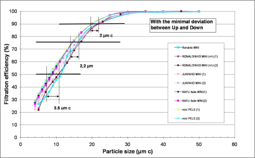
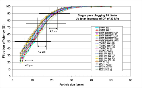
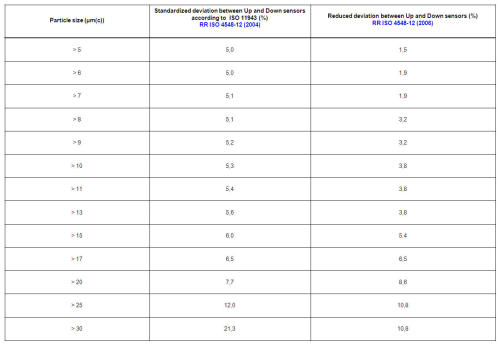
This last procedure has been used during international round robin testing with the aim of identifying the sources of variability in combustion engine lubricating oil filter ratings. [Figure 1] and [Figure 2] show that by dividing them by two, the variations accepted between online calibration of the two sensors lead to a reduction from ± 3 μm(c) to ± 1μm(c) in the differences between the filter ratings. If not important as such, these differences may have a strong impact on the filter trade and trust in the relationship between filter manufacturers and filter users. Numerical values are reported in Table 1.
Fluid Contamination Monitors (or Indicators)
These instruments, often referred to as Field Contamination Monitors (FCMs), are used to cautiously monitor the level of particulate contamination of fluid systems during their normal operation or during a flushing or rinsing process.
International standards have been recently adopted to give users of such instruments guidelines for their choice, proper use and verification, if not calibration.
ISO 21 018 has been designed in a number of parts:
• Part 1 (published) gives an overview of principles and techniques of particulate contamination detection, sizing and analysis.
• Part 2 (being drafted) should state the principles of verification of particle size measurement and analysed volume, determination of operating range, reproducibility and resolution.
• Part 3 (published) describes instruments using the filter blockage technique.
• Part 4 (being drafted) should describe contamination indicators based on the light extinction principle.
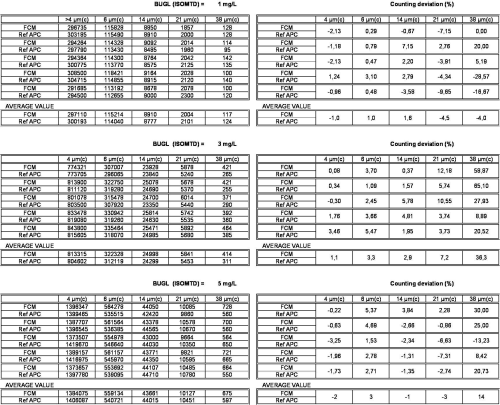
Even if many suppliers of such instruments claim they are particle counters, experts still discuss how to differentiate particle counters. This ranges from instruments capable of detecting particles one by one and then sizing them individually (calibrated per ISO 11 171), to contamination indicators or monitors, which only evaluate particle size distribution even if they report fluid contamination codes or classes as in ISO 4406 or ISO 11 218. Table 2 illustrates the difficulties for a FCM to be accurate at sizes of less than 38 μm(c).
A practical way of knowing if an instrument claimed to be a field particle counter is genuine would be to ask the supplier if filtration ratios or filtration efficiencies are accurate if measured on a multi-pass test stand equipped with two of the instruments, one upstream and one downstream of the test filter.
Verification procedure of FCMs
Even if they use the same particle detection principle as particle counters (the light extinction technique) FCM or CLI (Contamination Level Indicators) do not give the same kind of information. Their optics, electronics and hydraulics are not designed to the same level of quality. They evaluate the order of magnitude of particle sizes and numbers, and compare their value to standard tables and report ISO codes or classes. As such, they cannot be directly traceable to NIST SRM 2806 and few results can be verified to ISO 11 171.
Key performance verification procedures to be incorporated into ISO 21 018-2:
• Sample measurement volume accuracy.
Repeated analysis on a close loop validated per ISO 11 943 at different line pressures should allow determination of the variation of volume of samples analysed. It will depend on the equipment used to define the analytical volume. A volumetric device such as a piston or a syringe should be more accurate than a flow rate control device associated with a timer.
• Regulation of flow rate in the sensor.
Compared to laboratory particle counters, field indicators are intended to be installed on industrial circuits subject to flow and pressure changes susceptible to impact sensor flow rate or pressure and thus the volume of fluid actually analysed.
• Particle counting and sizing accuracy.
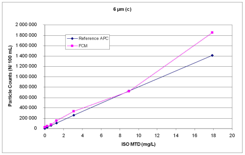
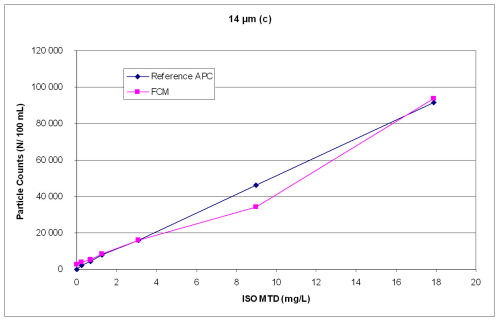
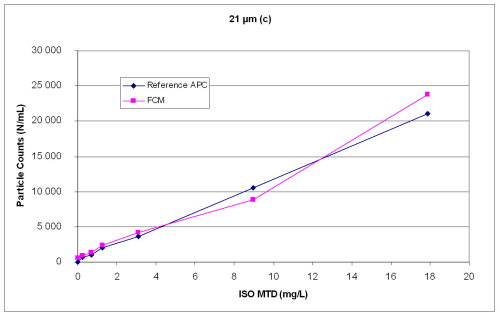
The use of secondary calibration suspensions with various contamination levels circulating in a closed loop as in ISO 11 943 (see Photo 1) should allow the determination of the operating range and the resolution or sensitivity in terms of contamination levels (see Figures 3a/b/c)
Validation of online particle counting/dilution systems
As already explained, the quality of multi-pass or more generally filtration efficiency tests of cartridge filters greatly depends on the accuracy of the particle counting systems, especially since the same errors are made twice, one upstream and one downstream of the test filter. In the case of testing coarse filters or when required by the standard applied, for example ISO 19438, to evaluate combustion engine fuel filters, an online dilution system is required.
This equipment samples the fluid in the test line, introduces a quantity of ‘clean’ fluid to dilute the sample and the mixture then flows to the sensor.
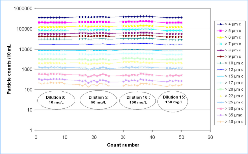
The validation of this complex hydraulic system, preferably installed in a movable cabinet (see Photo 2) to protect the particle counter sensor against any electrical noise and mechanical vibrations from all the electric/mechanical components of the multi-pass test bench, consists in verifying the stability of the flow rate to the sensor at various dilution ratios as shown in Figure 4.
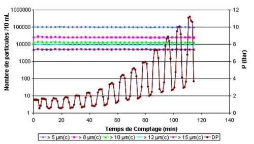
Another key step of the validation is to quantify the stability (variation) of the flow rate to the sensor when the line pressure changes. This always happens when measuring the efficiency of a filter during its life, which means when the differential pressure increases until the clogging/breakthrough pressure is reached. This is the case when performing the efficiency or multi-pass test in conditions of cyclical flow, i.e. the test flow through the filter constantly changes as stated in draft ISO 23369. That means that the sampling point pressure on the test line also changes and thus, without appropriate equipment and a rigorous validation, the flowrate through the sensor may change as well. Because line pressure changes upstream and downstream of the test filter are not similar, the upstream and downstream sensor flows change differently. Of course, this is what makes the particle numbers and filter efficiency values totally wrong.
The choice of hydraulic components is important to guarantee that in all conditions, flows through the two sensors are constant as illustrated in Figure 5.
Conclusions
Automatic Particle Counters and Fluid Contamination Monitors are widely used in filter testing and fluid contamination analysis laboratories and in industrial facilities to monitor filters and cleaning processes and machines.
If often using the same physical principles of particulate contaminant detection, their optics and electronics do not have same characteristics of accuracy and repeatability. A Fluid Contamination Monitor cannot be considered a true particle counter as shown by the refusal by their manufacturers for their use on multi-pass test benches. Instruments have to be regularly calibrated, validated or compared to a ‘reference’ instrument traceable to certified particles.
When evaluating the performance of a filter element, such instruments are used simultaneously upstream and downstream of the test filter. Reliable results are achieved only if they are calibrated and matched. When test contaminants are used at a concentration higher than the saturation level of the sensors, a dilution is needed. Such a process requires equipment that is proven to ensure a constant flowrate through the two APC sensors, whatever the line pressure or flowrate.


