First stage (anaerobic) biological treatment
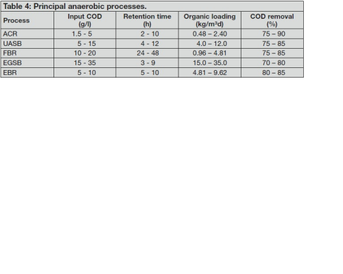
The principal anaerobic processes available for consideration include: • The Anaerobic Contact Reactor (ACR), • The Upflow Anaerobic Sludge Blanket (UASB), • The Fixed Bed Reactor (FBR), • The Expanded Granular Sludge Reactor (EGSB), and • Expanded Bed Reactor (EBR). The process efficiencies in terms of COD removal for these systems are typically as shown in Table 4 [3]. The two processes that can handle the highest levels of COD in the influent are the UASB and EGSB systems.
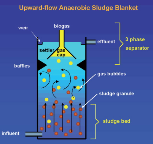
UASB process
The Upflow Anaerobic Sludge Blanket (UASB) technology, normally referred to as a UASB reactor, is a form of anaerobic digester, which is a methanogenic (methane-producing) digester. The process forms a blanket of granular sludge, which is suspended in the tank. Wastewater flows upwards through the blanket and is processed (degraded) by the anaerobic microorganisms. The upward flow combined with the settling action of gravity suspends the blanket with the aid of flocculants. Biogas with a high concentration of methane is produced as a by-product. Solids requiring a high degree of digestion can remain in the reactors for periods of up to 90 days. A Gas Liquid Solid separator (GLSS) provided near the top of the reactor, enables sludge to settle into the blanket, biogas to escape into the dome at the top of the reactor and treated supernatant to flow out of the reactor. High sludge concentration in sludge blanket and low concentration of suspended solids in the reactor overflow are characteristic features of a good UASB. A schematic of a UASB unit is shown in Figure 6.
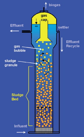
EGSB process
This system was developed to overcome problems such as preferential flows, hydraulic short cuts and dead zones that can occur in other anaerobic systems. By using granular sludge in the reactor and by using adequate height/diameter ratio or effluent recirculation, liquid upflow velocities of up to 10 m/h can be achieved, in contrast with the 0.5-2 m/h values applied in other units. This improves the sludge bed expansion and the bulk mixture that promote better biomass-substrate contact. These units can be operated at high pressure, in which case no gas holder or biogas compressor is required. This limits emissions of nuisance odours. A typical system is shown in Figure 7. Typical advantages of the EGSB system are stated to include: • Very high organic loading capacity (15-35 kg COD/m³/d); • Small footprint; • Highly settleable granular biomass; and • Methane by-product.
Second stage (aerobic) biological treatment
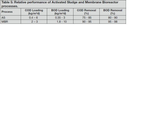
With the inlet COD load reduced by ~75% the second stage aerobic treatment system could be: • Activated Sludge (AS); • Membrane Bioreactor (MBR); • Tricking Filter (TF); • Expanded Bed (EB); and • Biofilter Fixed-Bed (BFB). However, reference 3 indicates that where both COD and BOD have to be removed from waters (which is the case here) then the reference document [3] had insufficient data on all processes so only either an Activated Sludge (AS) unit or a Membrane Bioreactor (MBR) unit could be considered. Were such data available then the data in Table 5 should be expanded to include these three processes into the selection process. However, as reference 3 is the preliminary design document for systems to be installed into oil and gas operations the selection process followed here has taken data only from that source for use in the following discussion.
Activated sludge process
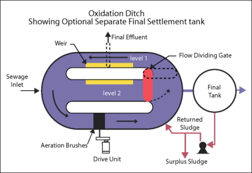
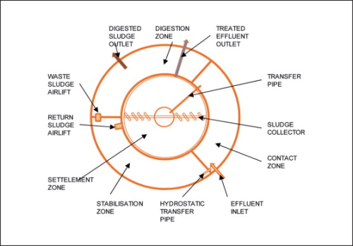
Activated sludge systems are well understood by the industry and there have been many journal articles covering all aspects of their design and operation. There are several variations on the basic activated sludge process: • Completely Mixed System - an aerobic system where the wastewater stream entering the aeration tank is rapidly distributed throughout the mixed liquor so that no pollution concentration gradient exists within the tank; • Plug Flow - an aerobic system where the wastewater stream and the return activated sludge (RAS) are mixed at the inlet of a long aeration tank or channel and the treated mixed liquor is withdrawn at the opposite end, theoretically creating a ‘plug’ moving along the tank; • Extended Aeration - an aerobic system where there is usually no primary settlement though screening/comminution/de-gritting should be considered essential to ensure effective operation of the plant; • Contact Stabilisation - the contact stabilisation (biosorption) process is an aerobic process that comprises treatment of the wastewater stream in three distinct stages. These are; Inlet Contact zone; Settlement zone; and Stabilisation zone. There is often a fourth stage for treatment of the surplus sludge from the plant (digestion). Should the option to use the AS unit for the aerobic stage of biological treatment be pursued then downstream filters may be required. Figures 8 and 9 illustrate examples of Extended Aeration and Contact Stabilisation systems.
Membrane Bioreactor (MBR)
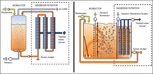
Again these systems are well known in the industry and this discussion will limit itself to their applicability for use onshore in the treatment of produced and other oil and gas terminal-derived waters. One of the key benefits of a membrane bioreactor system is that it effectively overcomes the limitations associated with poor settling of sludge in conventional activated sludge (CAS) processes. The technology permits bioreactor operation with considerably higher Mixed Liquor Suspended Solids (MLSS) concentration than CAS systems, which are limited by sludge settling. Increased Sludge Retention Times (SRTs) - usually exceeding 15 days - ensure complete nitrification even in extremely cold weather. A secondary benefit is that, as the sludge is kept in a single vessel some sludge digestion will occur, reducing the amount of sludge produced by the system. As the final stage in the process is membrane filtration there is no need for any additional filtration before the water is discharged. Figure 10 illustrates the two most common membrane bioreactor arrangements.
‘Frac’ waters
Much has been heard recently about these infamous waters, but it must also be borne in mind that the use of this commodity, albeit heavily dosed with chemicals and sand has contributed to a significant reduction in gas prices in the continental USA. As expected much has been written on this topic and some viewpoints from the oil and gas industry’s perspective are given in reference 4. A recent article in Filtration+Separation [5] provides an insight into a mobile treatment system for handling these waters. From available data the water returned to the surface can either be treated for re-use for fraccing or for discharge to the environment. In both cases the components which need removing are: • Dispersed hydrocarbons (oil and grease); • Heavy metals; • Suspended solids; • COD; and • BOD. Where the water is discharged to the environment additional (second stage) treatment may be required for the removal of: a) BOD; b) COD; c) Dissolved solids; and d) Boron. The first stage of treatment is very similar to that discussed for onshore produced and oil terminal- derived waters, i.e. first stage removal of hydrocarbons, second stage (if required) removal of heavy metals, a third/fourth stage of anaerobic/aerobic treatment to reduce the levels of COD/BOD and finally filtration. Stage two may require the removal of additional organic components by one or two stages of compact aerobic (for example MBR) treatment, a reduction in dissolved solids (RO) and finally removal of boron by ion exchange. Such treatment can provide final water having <100mg/l of dissolved solids, <0.75mg/l boron and residual organic components removed to below detection limits. A recent innovative development in the removal of organic species from flowback waters is the potential to use an advanced oxidation process in a batch-wise treatment mode. One unit supplied by Ozonix uses a combination of injection of in-situ generated ozone, hydrodynamic and acoustic cavitation plus electrochemical oxidation to produce the very reactive hydroxyl radicals in the reaction chamber. Chemical types present in frac waters which have successfully been eliminated by use of this system include: • Methanol; • Acetic and citric acids; • Isopropyl alcohol; • 2 butoxy ethanol; • Ethylene glycol; • BTEX species; • Biocides; • Diesel; and • Surfactants.
Coal bed methane
Similar to gas from shale deposits, methane produced from coal seams is becoming a more significant source of energy, not only in the continental USA but elsewhere in the world, especially in Australia. Water in coal beds helps to keep the source rocks under pressure and must be removed in order to lower the pressure, thus stimulating the desorption of the gas from the coal seams. As the production life increases, the volumes of water produced will typically decrease. Data from the US Geological Survey [6] indicate typical water to gas ratios ranging from 0.03 to 2.8 barrels of water per Million Cubic Feet of gas. The water produced along with the gas exhibits significant variations in its composition, not only between different basins but also within any one basin. Total Dissolved Solids (TDS) levels have been found to vary between a low of 200mg/l to a high of 170,000mg/l. Principal components in the waters include: • Sodium; • Bicarbonate; and • Chloride Where the gas and water are separated either at individual wellheads or at clusters of wells, the selection of materials is critical. As is well known high salinity waters and carbon steels are not happy companions and dosing corrosion inhibitors can be counter-productive if the use of RO/ED or ion exchange membrane process is considered to reduce the salinity to the required level. Large organic molecules have been known to lead to fouling of the membranes, leading to their premature replacement. This also can apply to ion exchange resins where an upstream organic trap may be needed. Potential methods for the treatment of these waters include: a) Aeration - removes iron; b) RO - reduces TDS levels; c) Ion exchange - especially if boron is present; d) Electrodialysis (ED) - reduces TDS levels; and e) Distillation - reduces TDS levels. The final destinations of the water after-treatment include: i) Ponds for irrigation; ii) Wetlands; iii) Injection; iv) Discharge to surface waters; and v) Water supplies. Whichever disposal route is pursued, the water quality will need to be controlled to comply with the relevant local and governmental standards.
Conclusions
Due to the (current) far more rigorous controls on oil and gas field waters disposed to onshore environments, greater emphasis is placed on reducing levels of dispersed hydrocarbons, heavy metals, BOD/COD organic compounds (especially the BTEX species) and, where appropriate, levels of TDS. Treatment processes are available to manage the satisfactory removal of these components but the selection of the optimum combination of processes has to be carried out with due attention to the prevailing (and possible future) environmental discharges in force.
References
[1] Treatment and Discharge of Produced Waters Offshore, Filtration+Separation, March/April 2013, pp20-23. [2] Reference Document on Best Available Techniques for Mineral Oil and Gas Refineries, European Commission Integrated Pollution Prevention and Control, February 2003. [3] Reference Document on Best Available Techniques in Common Waste Water and Waste Gas Treatment/Management Systems in the Chemical Sector, European Commission Integrated Pollution Prevention and Control, February 2003. [4] Handling Produced Water from Hydraulic Fracturing, Pam Boschee, Oil & Gas Facilities, Editor, Society of Petroleum Engineers, Oil and Gas Facilities, February 2012, also: SPE 119898, Marcellus Shale Water Management Challenges in Pennsylvania by A.W. Gaudlip, Range Resources Appalachia LLC, et al. SPE 119478, Frac Fluid Recycling and Water Conservation: A Case History by D.V.S. Gupta and B.T. Hlidek, BJ Services. SPE 121104, Breakthrough Mobile Water Treatment Converts 75% of Fracturing Flowback Fluid to Fresh Water and Lowers CO2 Emissions” by Aaron D. Horn, Newfield Exploration Mid-Continent. SPE 125336, Optimizing Fracturing Fluids from Flowback Water by S.M. Rimassa, Schlumberger, et al. SPE 141448, Water Recycling and Purification in the Pinedale Anticline Field: Results from the Anticline Disposal Project by L. Shafer, Integrity Production Services. The Shale Revolution, R Jansen, The Chemical Engineer (Journal of IChemE) Issue 863, May 2013 pp 34-37. [5] Mobile Water Treatment Tackles New Oil and Gas, Filtration+Separation, March/April 2013, pp24-25. [6] USGS Fact Sheet FS-156-00, November 2000.
Contact: David Robinson C Eng, MIChemE The author retired as a water treatment specialist with Genesis Oil and Gas Consultants in August 2008. He started his career in the water industry with William Boby in 1970, before moving to the Portals Group in 1972. He has spent the last 25 years as a consultant to the oil and gas industry, with Oil Plus and then with both Altra and Genesis Consultants. During his career he has written and presented many training courses for oil and gas companies worldwide.
Read Oil and gas: Treatment and discharge of produced waters onshore (Part 1)


