Introduction
Advances in computer technology, improvements in the underlying science and the application of two- and three-dimensional computational and design software, are helping to generate savings upwards of millions of dollars in oil and gas industrial applications. These savings can be achieved when engineers employ tools that enable them to much more completely understand and visualise the internal workings of their equipment and processes as well as to develop numerical experiments that improve the reliability, performance and quality of this equipment. Oil and gas extraction improvements are achieved through new technology development, which in turn is driven by engineering and scientific innovation. Current production realities (smaller oil fields, deeper fields, horizontal drilling, etc.) combined with tighter environmental concerns and operating practices have brought filtration and separation practices to the forefront in the oil and gas extraction sector.
Engineering simulation covers multiple engineering disciplines and various aspects of design and analysis: for example, structural, thermal, fluids and electromagnetic applications. There are two current trends in engineering design: performing upfront analysis, called Simulation Driven Product Development™, and predicting accurate interactions between various disciples, called multiphysics simulation. The benefits include the ability to develop insight into product performance early in the design cycle, reduced prototyping costs, and accelerated time to market. Additionally, multiple influencing parameters can be evaluated together to simulate real-life situations more closely.
In the oil and gas industry, specifically the filtration and separation of produced water and sand management, engineering simulation can enhance the operational performance and effectiveness of equipment. Simulation enables engineers to create a virtual prototype of the product/process, which enables the study of significant operating variables and their influence on the product/process performance. Engineering simulation tools assist companies in evaluating and assessing feasibility as well as reducing risk and increasing reliability of equipment and processes.
One fast-growing area of engineering simulation is the use of computational fluid dynamics (CFD). This article provides an overview of how this technology is assisting oil extraction by focusing on separation examples applicable to produced water and sand management.
Flow modelling and engineering simulation technology is becoming an integrated part of better equipment design and improving performance. Using this technology, engineers are able to clearly see the effects of physical phenomena such as flow distribution, mixing, separation, heat transfer, reaction, erosion, particulate accumulation, and species concentration. CFD allows engineers to include particle size distribution in their design considerations. Through use of this technology, it has become increasingly possible to optimise product design and efficiency and reduce overall cost. Engineering analysis software enables engineers to move beyond the rules-of-thumb and empirical correlations (not to mention expensive physical testing) to meet the ever-increasing engineering challenges in oil extraction — especially for offshore applications and resources in deep and ultra-deep waters.
One of the undesirable products of oil and gas drilling is produced water, which must be disposed of. The water must be separated for transport and/or reinjection into the formation, or “polished” of any residual oil if it is to be disposed — whether the application is onshore or offshore. For onshore operations, there are additional options for processing and/or reusing produced water. Because produced water often contains oil and heavy metals, the discharge and reuse of produced water is controlled by environmental regulations. A variety of equipment and processes, including hydrocyclones, membrane separation, and other separation methods, are used to treat produced water.
Similarly, sand production is often inevitable, especially in low-formation strength fields and some rock fractionation applications. Prediction of sand settling and erosion rate along with critical flow rates to help prevent settling in horizontal pipes bends and other piping systems are required for developing effective sand control procedures, delaying erosion, reducing inspection and helping to reduce and eliminate interruptions. Various types of equipment use combinations of screens, filters and gravitational separators to help remove and manage sand.
Application examples
To help illustrate the benefit of engineering simulation for fluid mechanics-related applications, this section covers application examples of gravitational and membrane separation simulation including an erosion study. Gravity separators: cyclone/hydrocyclones
Hydrocyclones have been in use in industry for decades, but there are still challenges in designing the devices to operate efficiently in separating oil and water over wider cut ranges and increasingly higher flow rates. The performance of a hydrocyclone is highly sensitive to the geometrical shape and operating parameters as well as phase concentrations and dispersed droplet and particle size.
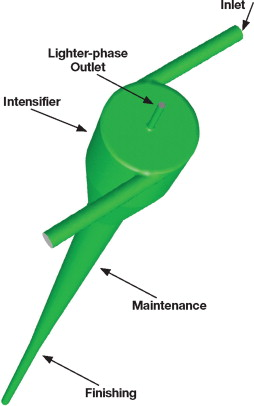
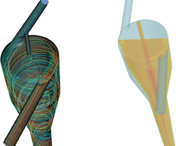
Engineers have employed CFD simulation technology to design hydrocyclone separators for desired efficiency and performance. CFD simulation can provide valuable guidance in determining the overflow and underflow recovery ratio at given operating conditions. Fluid dynamics also can produce a complete picture of complex hydrodynamics, such as radial profiles of mean swirl, axial velocity components, and distribution of turbulent kinetic energy with the separator. Figure 1 illustrates typical hydrocyclone geometry for oil-water separation, and the simulation results (Figure 2) show oil droplet trajectories and the oil-phase distribution in the hydrocyclone. CFD also is being applied to engineering and design concerns such as improving inlet configuration and adjusting geometry for higher angular velocity, evaluation of separator performance over a range of flow rates, and developing multi-stage design concepts.
In the oil and gas industry, erosion problems are ubiquitous in production and processing applications. The transport of the particulate, usually sand, causes sand-metal collisions leading to erosion and wastage of the pipes and handling equipment. Increasing the transport velocity of the carrier phase increases erosion rates. Erosion can lead to substantial and costly maintenance and shut down or, in the worst case, an accidental pipeline rupture leading to equipment and environmental damage and possible human fatalities.
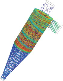
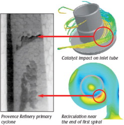
CFD simulation can be used to find the erosion rates for different field conditions and to optimise the production, operation, inspection and maintenance of equipment. With careful validation, the maximum erosion in complex equipment geometries can be predicted to within a factor of two to three. It is possible to account for the presence of particulates and their size distribution in many gas-solid flows and certain gas-solid-liquid or solid-liquid simulations. The presence of solid particles is treated as an additional dispersed phase, enabling exchange of momentum, mass and energy with the continuous phase as required. Figure 3 shows an example of transit fluid mechanics simulation of cyclone separators with particles of different size (coloured by particle diameter). Benefits from such a simulation include geometry optimisation, understanding and delaying erosion, increased separation and collection efficiency, and optimisation of cyclone operation. Figure 4, a refining cyclone separator, shows how well the engineering simulation has matched the erosion location, with areas of high recirculation at the inlet.
Membrane separation
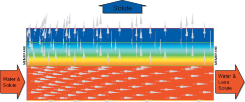
Gravity-based or centrifugation-based separation is not applicable when the contaminant in the water stream is dissolved. Membrane separation can be employed for such applications. Produced water can be treated with membrane filtration to desalinate the water. Essentially, membrane filtration involves simple migration of a solute species across a semi-permeable membrane as a result of a concentration differences on the two sides of the membrane. Figure 5 is a sample image from a CFD simulation of a membrane filtration. Even though it is not a specific oil and gas application, it illustrates the concentration distribution of water (red) and solute (blue) with vector arrows showing the movement of fluid in the system. The application of engineering simulation here yields a better understanding of the influence of solute concentration, flow rate, pressure differential, and geometric attributes of the filtration device. In addition, the simulation results can be used to optimise load loss along the membrane fibre and assist in obtaining uniform filtration and efficient membrane cleaning.
Offshore separators
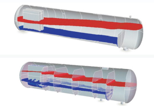
Separator design for offshore facilities, such as FPSOs and offshore platforms, is subject to a unique set of constraints imposed primarily by motion of the vessel to which the separators are attached. Typically, these separator units are horizontal vessels with internal baffling. The units rely on their hold-up capacity to produce the residence time necessary to separate the phases (gas, water and oil) by gravity. Disturbances to settling behaviour, such as separator motion, can increase the residence time required for separation and might cause short-circuiting and unnecessary mixing, leading to a reduction in separator performance. Using CFD simulation, engineers are able to simulate the full-scale separator and to estimate hydrodynamic forces caused by sloshing when the unit is exposed to six degrees of freedom motion. Figure 6 shows the simulation results from a dynamic CFD simulation of a gas-water-oil separator undergoing ship motion. The interface between gas-oil and oil-water are shown for two scenarios: without internal baffles and with internal baffles. Without baffles, the surface deformation is significantly larger than with baffles. Using CFD simulation to achieve optimal separator performance, different baffle and internal arrangements can be designed and tested to evaluate the damping behaviour. Other benefits that CFD simulation can realise include optimising the shape and location of inlets and outlets.
Summary
Engineering simulation is becoming an essential tool for engineers in the design and analyses of filtration and separation equipment. The appeal is to provide insight and to enable better understating of how reliably equipment will perform and meet tighter engineering and environmental requirements at a lower cost. This article provides a brief introduction of engineering simulation in fluid mechanics, with examples of how complex multiphase flow problems can be modelled to gain insight in the separation processes.
Contact: Senior Marketing Specialist, ANSYS, Inc., Tel: + 1 724-514-2967, www.ansys.com


