
With the shift to machine electrification there arrives an opportunity to take advantage of redesigned hydraulic components. Using the latest computer simulations, it becomes possible to optimise the hydraulic tank, for example: a task that not only provides more space for extra battery capacity, but also delivers a host of additional advantages that include reduced fuel consumption, less CO2 emissions (for diesel powered vehicles), improved safety, lower manufacturing costs, reduced maintenance costs, less environmental impact and lower total cost of ownership.
Using virtual reality for design and development is fast and cost effective, and while it does not replace conventional prototyping and testing, it can substantially reduce development time and the number of iterations required, accelerating time-to-market for OEMs. Simulations also suggest suitable materials, appropriate tolerances and adequate manufacturing methods, leading to the efficient management of engineering resources.
Virtual engineering, in particular computational fluid dynamics (CFD), is highly effective at optimising the design of hydraulic tanks, beginning with a dramatic reduction in aeration.
Via the return line flow, hydraulic tanks are subject to contamination by foreign matter of different physical and chemical properties. Although it is possible to separate solid contaminants from the oil stream using a return line filter, any air bubbles inevitably pass through the filter and enter the tank, and then the suction line. To complicate matters further, the structural behaviour of the tank in response to the flow pressure and variable thermal loads constitutes a multi-physics problem involving the aspects of sloshing, bubble formation, turbulence, heat transfer and structural dynamics.
Put to the test
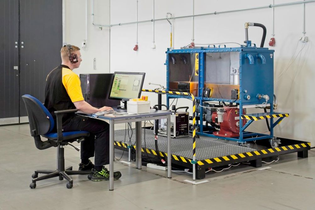
A recent case study performed by the Filtration Group of Parker Hannifin set out the benefits that CFD can provide in optimising the design and development process of a hydraulic tank.
In the first instance, consider that the inlet configuration of a hydraulic tank has a direct influence on the overall flow pattern and affects the force acting on the tank’s internal surfaces. As part of the study, Parker designed the tank with the potential to alter the funnel positioning. Five funnel configurations allowed the team to investigate the effect of inlet properties on the flow pattern: funnel at 0º (with angled open bottom); funnel at 90º; funnel at 180º; perforated funnel at 0º; and perforated funnel with flat bottom.
The results of the computer simulations produced interesting outcomes, with significant differences in the amount of swirling, mixing and sloshing of hydraulic fluid. As a point of note, the amount of air reaching the critical region reduced with the turning of the funnel angle. Furthermore, the strength analysis based on the CFD-predicted pressure imparted to the internal walls of the tank included the magnitude of the resulting stresses and deformation of the structural material. This enabled the identification of critically loaded/displaced locations and the evaluation of structural safety.
Further useful observations resulting from the simulations included the effect of funnel position on shear stress distribution, tank wall skin friction and heat transfer.
Among other effects, the funnel designs with flow exiting through perforations had a significant impact on flow momentum, resulting in improved oil stream distribution within the tank.
Real world benefits
CFD is becoming increasingly vital in the process of design and development tasks such as hydraulic tank optimisation as it delivers numerous benefits to machine OEMs and end users. Many of these advantages derive from a significant reduction in tank weight and footprint, with increased battery installation capacity a notable example.
The process of redesigning previously diesel-driven machines into battery-operated electric counterparts must typically take place without changing the outer shape. With such a constraint, it is often difficult to find sufficient space to accommodate a battery pack. However, reducing the footprint of the hydraulic tank makes space for more battery capacity, helping machines to run longer on a single charge. In the Parker case study trial, it was possible to reduce hydraulic tank footprint by 75 litres per machine. Alternatively, a reduction in vehicle weight can potentially increase its load capacity, meaning engineers can optimise the design according to individual machine requirements.
With regard to weight, there are well-documented savings in both fuel consumption and CO2 emissions through the application of lighter components. Parker’s hydraulic tank optimisation case study showed weight savings of 100 kg per machine, helping to drive up fuel efficiency and cut down carbon emissions.
Safety is another factor to gain from hydraulic tank optimisation. The major area of focus here is reducing the aforementioned aeration. When activating a hydraulic cylinder, for example, the pump essentially sucks oil from the tank into the system. However, when the hydraulic fluid returns to the tank, it typically features aeration. Failing to eliminate this air before it enters the suction stream will lead to distribution throughout the hydraulic system, which can potentially disrupt machine handling and movement. With tank optimisation, the potential exists to reduce any air contamination entering the suction stream, close to 0%. Such an outcome leads to enhanced machine operability, as well as better safety for the operator and any workers in the area.
Cut manufacturing costs
An additional saving is available through lower manufacturing costs. Reducing the size of the tank via optimisation can cut the amount of steel by around 30%, saving on both material and welding costs. This outcome also reduces the amount of hydraulic fluid required and, in turn, the effect on the environment. In Parker’s hydraulic tank optimisation case study trial, it was possible to save 500,000 litres of hydraulic fluid per machine series, per year. In total, the trial demonstrated projected savings in steel and fluid of circa €1 million per machine series over the course of a 12-month period.
Maintenance costs also decrease. As well as interfering with machine handling, air within the system can have a negative effect on the service life of sensitive hydraulic components. Hence, through tank optimisation (and its ability to reduce aeration), end users will experience a reduction in maintenance costs. In mobile equipment, the number one failure is typically the hydraulic pump. This component is expensive to repair or replace, while its failure will also necessitate significant machine downtime. Any downtime is costly, particularly on 24/7 mining or quarrying sites, for example.
CFD provides a myriad of further focus areas, including heat distribution. Tank optimisation through simulation helps to distribute heat evenly, reducing fluid temperature before it enters the system. Fluid properties suffer negative effects from excessive temperatures, which again can compromise component service life.
Another advantage of simulation is the potential to improve flow distribution from the return filters into the suction stream. As part of the tank optimisation process, Parker will design purpose-designed internal baffle plates that guide the oil on the best flow path. As well as optimising flow streamlines, the baffle plates help with heat dissipation and deaeration.
The future of product development
In mobile hydraulic systems, where manufacturers aim at reliable, efficient yet cost-effective solutions, the predictive capabilities of state-of-the-art computational tools at real-world accuracy enable design engineers to understand the coherent phenomena and make rationale-based decisions during system development.
These physics-based simulation technologies are likely to promote collaborative product development practices between CAD, PDM and supplier management systems, and hence realise innovation in response to engineering requirements. Most importantly of all, the benefits for OEMs and end users are both tangible and sizeable.
Sietse Baars is Market Development Manager – Mobile, Hydraulic and Industrial Process Filtration Division EMEA (HIFE), Filtration Group, Parker Hannifin.


