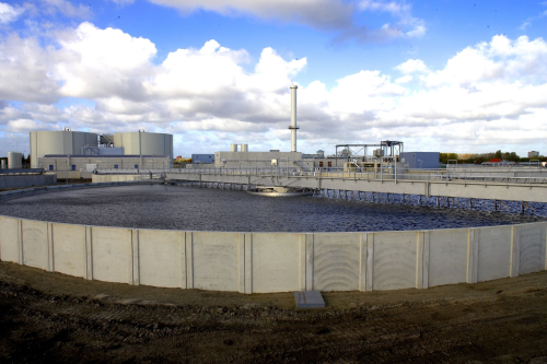
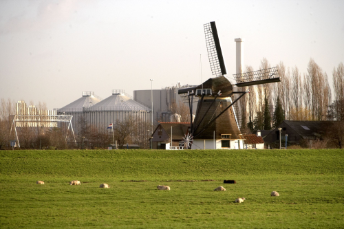
The Harnashpolder wastewater plant, based The Hague, The Netherlands, is one of the large wastewater treatment plants in Europe and has a very high level of environmental protection, with particular emphasis on the reduction of phosphorus and nitrogen discharge into the natural environment. The plant also uses biogas, from sludge fermentation, to generate energy.
The plant is compliant with new European standards which in turn helps the country comply with new, stricter European guidelines in the area of wastewater purification. Along with the Houtroust plant nearby, it will serve a population of 1.7 million, and will purify 80% of wastewater in the region of The Hague.
Harnaschpolder was designed by Veolia Water Solutions and Technologies (VWS), a subsidiary of Veolia Water. The plant is the first ever public-private partnership in the water industry in the Netherlands and was built by the Delfluent Consortium with Veolia Water as a 40% shareholder. The Consortium will operate both the new Harnaschpolder and the existing Houtrust plants and sewage systems for 30 years. The 30-year, €1.5 billion contract was created in 2003 to design, build, finance and operate the plant.
Plant construction
The construction was split into two phases, the first being the construction of the new wastewater treatment plant, and the second the adaptation of the existing Houtrust plant. Both plants make use of the same principles for their purification processes.
This type of DBFO (Design, Build, Finance, Operate) contract also includes the operating and standards compliance of the existing plant at Houtrust (The Hague) for a period of thirty years.
The civil and architectural activities were carried out in a bunded (walled) area consisting of sheet piled walls. After demolition of existing buildings, earthworks were carried out to achieve the required ground levels followed by the underground drainage system installation. Foundation works also started at the same time.
In all, 33 tanks have been built, with diameters varying from 18 to 64 m. The concrete inner and outer walls have an average height of 4 to 9 m and the walls of the silt fermentation tanks are the highest at 20 m. Floors have an average thickness of 40 cm. A number of the tanks have a sloping floor in the middle (waste pipe) and a concrete overflow gutter in the tanks ensures a separation of waste and cleaned water. Some tanks are provided with a cover (concrete, synthetic material or metal), to aid the cleaning processes and/or to lessen the smell.
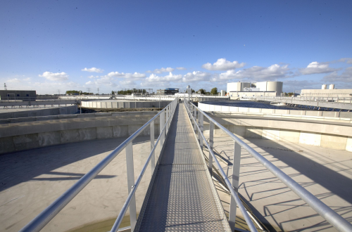
Next to the tanks, around 20 platforms and buildings have been built, with several divisions ensuring that wastewater and silt are separated. The necessary processed air for the biological tanks is prepared in the blower building and there are five other installations which process the silt.
The influent pipe arrives at the entry point of the installation. From here, the wastewater is led to various pipe casings, both square and round, through the plant. Pipes running in the same direction are brought together in multi-cell pipe casings – a total of 2400 m of casings have been prepared.
Processes
Three processes are incorporated within the project:
- 1. Water treatment;
- 2. Sludge treatment;
3. Air treatment.
Collected wastewater (the influent) enters the installation and after biological treatment, clean water (the effluent) is returned to the sea. The biological treatment of wastewater, treatment of the sludge (by product) and gas all take place within the treatment process.
The influent is collected from the Hague region and neighbouring towns and is pumped to the wastewater treatment plant by means of large pipes. After biological treatment, clean water is pumped into the sea.
The first part of the process involves sieving the rough and fine solid parts of the wastewater, combined with four primary settling tanks and the second part of the process takes place in eight biological tanks. This biological treatment is mainly intended for removing carbon, phosphorus and nitrogen while complying with to the stringent European Law and regulations.
For the biological treatment, activated sludge treatment is used. This method requires the aeration tanks to be provided with air after which the solid parts (sludge) in the water can settle in the clarification tanks. The created effluent will be pumped straight into the sea with the level of purification being checked several times a day. The treatment process makes sludge into a bi-product which has to be dewatered away from the plant for storage or other purposes.
Sludge treatment is the third step of the wastewater treatment and also covers the sludge from the primary settling tanks. To reduce the amount of sludge that has to be stored and transported, this treatment includes sludge thickeners, sludge digestion and dewatering equipment. The dewatered sludge is temporarily stored within the plant and will subsequently be disposed in lorries and skips.
While the plant is primarily focussed on the treatment of influent water and sludge, almost every part of it also produces dirty gas. To reduce the odour both inside and outside the buildings, an air treatment system has been installed, which combines the foul air extraction and the inlet of fresh air at any required moment. The foul air is biologically filtered before it is returned into the atmosphere.
Pre-treatment
The pre-treatment in the Harnaschpolder wastewater treatment plant consists of screen-waste removers and primary settling tanks. The dirty water enters the plant by means of two delivery pipes that form the end of the inflowing transport system. The mechanical treatment takes place immediately after the inlet, and the inflowing water flows through fine screens which have mesh widths of 6 mm. The screen waste is taken to a compactor by means of screw conveyors, and is compressed then stored in containers for transport. It is then incinerated outside the wastewater treatment plant.
After passing through the screens, the influent ends up in four primary settling tanks. In the tanks, particles that can be settled and part of the suspended particles are settled and the sediment – the primary sludge – is pushed to the middle of the tanks with a scraper, collected in a tank, and pumped to the sludge treatment building. The pre-treated water falls over the edges of the tanks and flows via a distribution system to the biological tanks.
Biological treatment
The Harnaschpolder wastewater treatment plant operates with eight biological tanks and it is the role of the distribution system to distribute the flow evenly over the tanks. The biological tanks deal with further purification of the dissolved dirt. The amount of time the water stays in the various zones of the tanks, along with the different types of bacteria practically guarantees the removal of all contaminants, including organic, nitrogen and phosphate.
The first zone of a biological tank consists of a selector that is used to produce sludge that can be settled. By supplying this sludge with a high concentration of nutrients, such as organic dirt, in this part of the process, it is possible to prevent the formation of filaments. The second zone of the tank is an anaerobic zone which optimises the biological phosphate removal. If measurements indicate that there is still too much phosphate in the purified wastewater, iron chloride is added to settle the phosphate with the ferrous ion.
The third zone of each biological tank is an aerobic-anaerobic zone, with aerobic periods leading to bacteria absorbing the biological contamination and the oxidation of organic nitrogen into nitrates. An anoxic period, without aeration, follows after every aerated period and ensures the consumption and conversion of oxygen-containing nitrates, whereby nitrogen gas returns to the atmosphere after denitrification. After the long journey through the biological tank – about 22 hours – the water, although still mixed with active sludge, can be deemed clean.
Next, large air blowers use membrane aerators at the bottom of the tank to provide the aeration system of the biological tanks with air. The aerators produce fine air bubbles from which the bacteria take the necessary oxygen to absorb the nutrients (dissolved dirt) and to multiply.
The mixture of water and sludge then passes through a quiet area, the so-called de-aeration tanks, so that the air bubbles do not disturb the next step. Next the mixture of active sludge and purified water flows over into the secondary sedimentation tanks. The sedimentation tanks ensure that the active sludge is sedimented, after which the purified water flows over the edge into the effluent pumping station. Each sedimentation tank has a reamer that pushes the sludge to the middle, to the sludge cone, after which connection pipe sends the sludge to the sludge pumps. Floating substances on the water table are collected in a tank and pumped to the sludge treatment.
The biological tanks need to have a sufficiently high concentration of active sludge to realise a high level of efficiency. The active sludge that flows away with the purified water to the sedimentation tanks returns to the biological tanks after sedimentation. This means the sludge pumps operate almost continuously to ensure that concentration in the biological tanks is always sufficient. This is the return-sludge circuit of the active sludge system.
When the bacteria eat various elements they start to grow, and this product of the treatment is called excess sludge. The excess of active sludge is removed from the wastewater purification process and excess sludge pumps are used to take it to the sludge treatment for processing. This is the how the phosphate stored in this sludge is removed biologically.
Effluent pumping station
The discharge of the purified wastewater, the effluent, takes place in two phases – from the Harnaschpolder to Houtrust and from there to the North Sea.
The clean water that flows from the secondary sedimentation tanks runs via chutes to the effluent pumping station, with a maximum flow rate delivered by gigantic pumps (13,000m3/hour each) via two underground delivery pipes to the effluent pumping station of Houtrust. The effluent pumping station there ensures that the purified water of both plants is discharged via a 2.5 km long pipe into the sea near Scheveningen. Because of the length profile and the placement of the pipes, pressure vessels are absolutely essential to protect the pipes against the consequences of possible water hammer. During this design therefore, the water flow through the Harnaschpolder wastewater treatment plant received special attention. As a result, the influent enters at a higher level, which means there is a natural drop ensuring that the water can flow to the effluent pumping station without requiring mechanical equipment and energy.
Energy from sludge treatment
The most important by-product of water treatment, after water, is sludge. Sludge does not leave the treatment plant directly, and can be used as a source of energy if it still contains a certain concentration of organic matter, and this is one of the roles of the primary settling tanks – to collect primary sludge with a large quantity of organic matter for sludge treatment. A second source of sludge is the biological treatment, although this so-called excess sludge is less rich in fuel.
The treatment of primary sludge starts with gravel and sand removal. This is done in the Harnashpolder plant with hydrocyclones, where a concentrated mixture of gravel and sand falls in a sand washer. After washing, this mixture is removed from the wastewater treatment plant.
The sludge flows over the hydrocyclones and flows to two thickeners – round tanks with scrapers where the sludge turns around for about five days. The sediment is separated from the water and the thickened sludge is pumped to the sludge fermentation tanks.
The excess sludge is a product of the biological treatment of wastewater. If the excess sludge and the floating substances contain too much water to enter the sludge fermentation tanks directly, they are thickened in thickening centrifuges in order to ‘wring out’ the sludge. Before the inlet to the centrifuge, a polymer is added to the sludge to obtain a better yield. The thickened excess sludge is ready for the sludge fermentation process.
Sludge fermentation
The objective of sludge fermentation is to consume part of the organic matter, which produces a reduction of the total volume of sludge that requires treatment. The second objective of the process is the production of biogas. Biogas usually consists of methane (65-70%) and carbon dioxide (35-30%) and contains small quantities of other gasses such as ammonia gas.
The sludge fermentation process is a biological and anaerobic process that works with specific bacteria at a temperature between 33-37°C. The process takes place in two large tanks, where the sludge stays for more than twenty days. The tanks are fitted with a heating system, heat exchangers and sludge recirculation pumps, and have thermal insulation. The heating system uses hot water from the biogenerators and does not require any additional energy.
To keep the process as efficient as possible, the content of the tanks is constantly mixed to ensure a good contact between the bacteria and the sludge. Because of the diameter of the sludge fermentation tanks, a good mixture is only guaranteed with biogas circulation – biogas is drawn in above the sludge level, passes through compressors and is then delivered into the tanks with sprayers.
Each sludge fermentation tank is equipped with an overflow pipe and a valve. Sludge passes through a drop pipe to the buffer tank for fermented sludge and is then pumped to dewatering centrifuges that operate along the same principles as the thickening centrifuges, albeit with a different type of polymer. The goal is to obtain dry sludge that can be incinerated after removal from the wastewater treatment plant.
Biogas
As the organic matter in a continuous process is ‘eaten up’, the process also continuously produces biogas. The biogas is collected above the sludge level, inside the sludge fermentation tanks, and is sent through a pipe to two membrane gas storage tanks. These play the role of buffer tanks and keep the system slightly pressurised. The membranes are surrounded by a steel construction that provides the mechanical protection.
Small compressors take the biogas from the storage tanks to feed the biogas generators where it is incinerated to generate electricity, which is used directly by the wastewater treatment plant. This green energy reduces the operating costs and gives the wastewater treatment plant a degree of independence. The thermal motors also produce heat that can be reused to ensure the sludge fermentation tanks operate at the correct temperature.


