A pdf version of this article is available in the 'Download' section on the right hand side.
Background
Selection of pre-treatment technology for desalination in seawater reverse osmosis (SWRO) applications tends to polarise opinion. Conventional technology represents the status quo while membrane filtration adopts the role of the challenger, with a rapidly developing track record. Two issues limit the wider adoption of membrane pre-treatment. Firstly it is considered expensive in terms of capital cost, though it does provide operational cost savings. Secondly there are misgivings about whether membrane filtration alone provides sufficient pre-treatment, since preparing a feed suitable for RO requires more than the removal of fine particulates.
This article is the second in a series which will examine the issues involved in the selection of pre-treatment technology for SWRO, and consider the case for conventional and membrane pre-treatment options. This previous article examined the issue of the treated water quality for the RO feed, while the focus of this article is Integrity and Disinfection. Future articles will cover Cost and Sustainability, and Markets and Experience. The articles will focus on the comparison between pre-treatment technologies.
Treatment requirements
The water market is normally divided into two broad categories which describe the customer base served, ie: the Municipal and Industrial segments. These two segments have significantly different treatment requirements. The primary objective of drinking water treatment is disinfection. The purpose of removing other water quality parameters mainly assists disinfection or improves the subsequent stability of the treated water. Improvement of the aesthetic quality of the water in terms of taste, odour, and appearance is a desirable side effect, but of secondary importance compared to the disinfection driver. Of course, if the source is saline, reducing dissolved species would also become a primary treatment objective.
In contrast, industrial water treatment usually has several treatment quality drivers, with strict limits imposed on particulates and dissolved species, dependent upon the application. Disinfection is then usually applied as a final treatment stage.
Seawater desalination does not fit neatly into the categories described, since the output of a typical desalination project may have several end users, both municipal and industrial. Treated water quality standards may therefore vary, but it is likely that disinfection will be required since some of the output may well be required for drinking purposes. Disinfection is therefore normally a critical treatment objective in SWRO projects.
Disinfection capabilities of conventional pre-treatment
The conventional pre-treatment processes that have traditionally been used for pre-treatment to RO desalination are similar to those used in normal drinking water treatment. Filtration processes such as sand filters and multi media filters do not provide an effective physical barrier to micro-organisms unless used in combination with a coagulation stage. The particle removal efficiency for an uncoagulated feed would be typically 70-97% at 5μm, thus a log removal value (LRV) of 0.5-1.5. Since bacterial spoors are normally less than 1μm, disinfection due to physical removal by media filters is of limited value.
Particle removal is improved markedly by coagulation since particle size increases and the flocs formed tend to stick to the media surfaces, typically improving removal efficiency at 5μm by 1 LRV to 97-99.7%. The removal of bacterial spoors and even viruses is also improved, achieving a reasonable level of physical disinfection. However, conventional drinking water treatment relies on disinfection with chlorine as the final step, and the primary purpose of coagulation and filtration is to improve disinfection efficiency. Indeed, conventional processes rely on super chlorination of surface water supplies to guarantee disinfection, necessitating the use of high chlorine doses and a significant contact time.
In addition to the use of chlorine for disinfection, oxidation improves the efficiency of both coagulation and filtration processes, with the result that sometimes chlorine dosing is incorporated into conventional pre-treatment design[[1] and [2]]. However, the problem for desalination processes is that thin film composite spirals, which are by far the most commonly used RO membrane, are highly sensitive to chlorine. Oxidative attack degrades performance and increases salt passage. Furthermore, if the pre-treated feed is chlorinated and then dechlorinated, bio-fouling potential is increased, as discussed in the final section. Conventional pre-treatment therefore does not provide a disinfected feed supply to the RO, and the option of chlorine use is likely to be detrimental.
RO membrane integrity
RO provides a reasonable degree of micro-organism removal, but neither the RO membrane element nor the RO system is designed to provide a guaranteed disinfection capability. Though RO membranes are almost three orders of magnitude finer than the UF membranes used in the water industry, a typical RO system provides an inferior disinfection barrier. This section discusses the reasons for this apparent anomaly.
A thin film composite membrane used for RO is designed to reject salt at an efficiency of about 99% (ie: 2 LRV). If there are small defects in the flat sheet, the effect on removal efficiency will be small. Therefore, casting technology has developed to make a thin high performance active layer to achieve high salt rejection, but tolerates minor physical defects. When the flat sheet is wound into an element, the feed channel is sealed by the application of a glue line on the active layer surface. The supporting substrate is not sealed by glue penetration since the active layer is dense rather than porous. Any defect in the active layer therefore has a leak path which is not restricted to the local area around the defect.
Spiral elements are mounted in a pressure vessel with large diameter gasket seals. During operation, elements move their position in the vessel, and local leaks from feed to permeate can occur. Conductivity sampling is used to identify the more significant faults, but minor leakage has a limited effect on salt passage, and is tolerated. A survey of challenge tests with RO elements has shown that virus removal varies widely[3]. Whereas pilot systems can achieve > 6 LRV of virus, larger systems provide variable results, with LRVs as low as 2 or less, and an average performance of around 3-4 LRV.
A disadvantage of spirals is that if an element is found to contain a defect, it cannot be repaired, but could be replaced completely if performance was sufficiently poor.
The use of membranes for disinfection
Membrane filtration products have been specifically designed to provide an essentially complete barrier to micro-organisms. Some products guarantee this performance and are used to provide a sterile filtrate. One of the earliest commercial applications of membranes was for the removal of bacterial organisms in the bio-pharmaceutical industry in the 1950s. These microfiltration (MF) membranes were used in a dead end configuration, and provided a guaranteed removal of organisms at 0.22 μm and 0.45 μm, producing a sterilised filtrate.
Another critical application of membranes for guaranteed disinfection was developed for the microelectronics industry in the 1980s, in which a low molecular weight ultrafiltration (UF) membranes with a nominal molecular weight cut off of between 6k and 13k were used in a dead end configuration in the washwater polishing loop of wafer fabrication processes.
Membranes in general water treatment applications differ from these examples in that they are used in continuous processes, normally operated in a dead end mode with intermittent backwash. Although the membrane rating of UF and MF is below the size of bacterial organisms, minor imperfections will allow micro-organisms to pass through occasionally. Furthermore, the nature of the design of continuous processes creates infection opportunities. UF and MF processes therefore cannot achieve sterilisation, but may approach the performance of a physical disinfection barrier, provided that they maintain their integrity[4].
Integrity properties of the hollow fibre module
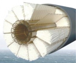
Membrane filtration systems used in the water industry nearly all use a hollow fibre module format. Hollow fibre modules use capillary membranes with an inside diameter normally in the range of 0.5-1.0 mm. The configuration may supply feed to the inside of the fibre or the outside. The outside feed configuration is split further into pressure driven formats in which the feed side is pressurised, and submerged, in which the driving force is supplied by applying a vacuum to the permeate side. Figure 1 shows a pressure driven inside feed format module. In the example shown, each of the 12 segments contains about 850 membrane fibres.
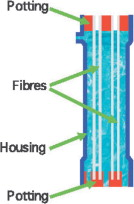
Hollow fibre membranes have a higher degree of manufacturing integrity, and are produced with a relatively narrow pore size distribution. Minor defects can occur in the fibre wall, or there can be gross defects in the fibre, but these are not commonplace, and are mainly eliminated by integrity testing and repair at the end of the manufacturing process. Figure 2 shows a diagrammatic cross section of a pressure driven outside feed module, illustrating the potting interface at the top and bottom of the module which provides the seal between feed and filtrate side of the membrane.
The design of the hollow fibre module preserves the intrinsic integrity of the membrane fibre using a potting material to seal the fibre with epoxy or other sealing compound. The potting material is able to penetrate the fibre completely since the UF/MF membrane is porous and allows the epoxy to flow through the membrane wall. Therefore, if there is a defect in the active layer of the membrane, the leak path to the product side is eliminated by epoxy penetration of the supporting membrane layer.
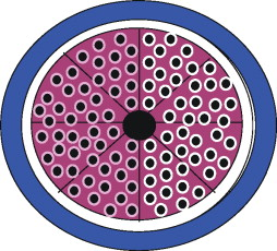
Figure 3 shows a cross section through the potting at the top of the module. The diagram illustrates a successful potting on the left hand side, in which epoxy has penetrated through the membrane support layer to provide a pale colouration through the fibre wall. In contrast, the right hand side illustrates an unsuccessful potting, which could occur if the epoxy was too viscous, or the active layer of the membrane too dense. In this example, the potting material has not penetrated through the fibre wall creating a potential leak path between feed and filtrate side should the active layer contain any defects. Sometimes early stage products from UF and MF modules manufacturers have contained some unpenetrated zones, but this is a problem that has been eliminated in established commercial products.
In module construction, some manufacturers manage to eliminate ‘o' ring seals completely to enhance integrity even further; if used, the key seal is much smaller in diameter than in the spiral element system, and a double ‘o' ring seal is used for increased security.
Fibre integrity failure modes
Fibre integrity problems can occur in UF or MF hollow fibre modules due to manufacturing defects, or defects caused by problems in process design or operation. Defects during manufacture are normally identified in a final stage integrity test, and repaired by pinning. A typical module of many thousand fibres may have one or two fibres pinned in the manufacturing integrity check.
With regard to operational issues, a major problem is failure of the strainer system (which will result in damage to the feed side of the fibre). Another operational problem is contamination of the permeate system. Integrity problems caused by particulates in the system and/or fibre weakness will tend to be exacerbated by over-pressurisation and water hammer. If valve sequencing is not carefully controlled, pressure spikes can be transmitted to the membranes.
Integrity verification
Verification of membrane integrity is an important issue for UF and MF technologies, since the provision of a barrier to micro-organisms is often the reason for selecting a membrane filtration process. The most common approach is to monitor filtrate quality continuously, and to conduct an occasional off-line pressure hold test. Turbidity monitoring is not sensitive enough to be a reliable indicator of integrity, and is not able to detect breaches that would reduce micro-organism removal below specification. However, it is inexpensive and reasonably reliable, and does provide some indication of changes in membrane performance.
The off-line tests are mainly based on the principle that water in membrane pores is held in situ by surface tension and capillary forces. The air pressure required to displace the water is known as the bubble point[4]. The most widely used of these tests is the Pressure Decay Test.
By using a monitoring programme, membrane filtration can provide a secure integrity barrier for water treatment applications. The barrier can be tested, and if necessary repairs can be performed to ensure that the barrier is maintained. Without membrane pre-treatment, a desalination system would rely on disinfection by chlorine of the final treated water, and depending on the source, may even need super chlorination. With membrane pre-treatment, the membrane pre-treatment stage alone provides physical disinfection, which reduces the reliance on final disinfection by chlorine and improves the operation of the RO.
Bio-fouling
Bio-fouling is one of the most difficult problems for an RO system, especially with warm feeds, above say 25°C. Bacteria are always present in a desalination system, since even the finest pre-treatment rating will occasionally allow bacteria to pass due to defects or from damage leading to loss of integrity. If bacteria have a food source colonies will develop and bio-film will grow. It is therefore best to adopt a strategy of management and control rather than expect to eliminate bacteria completely. With the correct operating conditions, it should be possible to avoid the worst effects of bio-fouling.
An important requirement of pre-treatment is to avoid the presence of oxidising compounds. A chlorine residual has a straightforward detrimental effect, rapidly degrading the membrane and increasing salt passage. However, a Cl2 residual anywhere upstream of the RO may also be damaging, even if destroyed by a reducing agent prior to the RO, as shown in Figure 4[5]. Breakdown products of Cl2 and high molecular weight organic molecules are likely to form assimilable compounds, which are a nutrient source for bacteria, thus stimulating bio-fouling.
In addition, the use of oxidants to disinfect and control established bio-fouling may provide only a temporary reprieve since, if successful, the dead bacteria will provide a nutrient source for new colonisers[6]. However in all likelihood, surface bacteria will protect internal members of the colony to some extent, enabling rapid re-growth soon after the disinfection procedure. Bio-fouling control therefore benefits from a carefully developed strategy of accommodation and limitation rather than attempts to eliminate it completely.
One of the strategies to control bio-fouling is to use shock chlorination, ie: a high Cl2 dose on an occasional basis. This strategy is moderately effective in slowing down the rate of bio-fouling, but does not eliminate the problem. Another strategy is to use chlorine dioxide rather than Cl2[7]. This relatively new concept has shown promise on a limited number of plants where it has been used. ClO2 is a sufficiently powerful oxidant to provide a disinfection residual, but is not strong enough to form AOC, thereby depriving bacteria of nutrient. Although RO membranes have somewhat greater tolerance to ClO2 than Cl2, it is unlikely that a full residual could be used (as for example with chloramines in wastewater reuse applications). The optimum methodology to take advantage of this option has still to be developed, but membrane pre-treatment allows the potential to use less aggressive strategies especially if combined with coagulation.
Conclusions
• Conventional pre-treatment is often used for seawater RO systems, but relies on chlorination, and potentially super chlorination, to achieve disinfection of the final treated water.
• Membrane pre-treatment provides a physical disinfection barrier to the RO, ensuring a superior feed quality and reducing reliance on final chlorination.
• Membrane filtration modules can be tested for integrity, and if necessary repaired, to ensure that the integrity barrier is maintained.
• Chlorine is sometimes used to enhance the performance of conventional pre-treatment, but increases the risk of bio-fouling; membrane pre-treatment does not require pre-chlorination of the feed, and therefore minimises this risk.
References
1 JG Jacangelo and J Grounds, Properly designed conventional pre-treatment provides suitable water quality for RO, Desalination and Water Reuse 13/4 (2003), pp. 16–23.
2 N Voutchkov, SWRO pre-treatment: Choosing between conventional and membrane filtration, Desalination (a Filtration & Separation publication) 4/1 (2009), pp. 5–8.
3 M Kumar, S Adham and J DeCarolis, Reverse osmosis integrity monitoring, Desalination 214 (2007), pp. 138–149. Abstract | PDF (361 K) | View Record in Scopus | Cited By in Scopus (2)
4 Membrane Filtration Guidance Manual Alspach, B (Malcolm Pirnie), Vickers, J (SPI), EPA 815-D-03-008 (June 2003).
5 Biofouling in a Seawater RO Plant on the Red Sea Coast, Saudi Arabia Saeed, M O, Jamaluddin, A T, Tisan, I A, Conference Proceedings, IDA San Diego, Vol 2 Ref 1131 (1999) 207-221.
6 Bio-fouling: Open questions, insufficient solutions, innovative approaches Conference Proceedings, EDS Baden Baden, 281 (May 2009).
7 An Overview of the 150,000 m3/day Beckton Desalination Plant in London Moore, B J, Malfeito, J J, Conference Proceedings, IDA Dubai, (2009).
In the first SWRO pre-treatment article in the November/December 2009 issue, Figure 1 (page 30) was adapted from images originated by Dr. Steve Tarleton, Department of Chemical Engineering, Loughborough University, UK.


