Ultrafiltration (UF), as pre-treatment technology, has become the preferred choice over reverse osmosis (RO) for problematic feed water such as surface or wastewater. UF can provide superior water quality compared with conventional treatment and delivers a continuously good filtrate quality independent of feedwater characteristics caused by, for instance, seasonal changes.
In seawater applications UF is becoming more popular as well. This is due to the advancements in UF membrane technology and the scale of economies resulting from an increasing demand. Recent integral cost comparisons have shown that, when all cost components and impacts on the treatment steps downstream are taken into account, UF can compete with conventional pre-treatment technologies.
One of the largest seawater desalination plants in Europe where UF is installed is located in Italy. This UF system features two innovative technologies in the field of membrane and module design which particularly address the need for highest operational safety and low operating cost. In the following article, the project background and the overall plant design will be described in detail, and operational data from the pilots and full-scale plant will be discussed.
Focusing on environmental concerns
The new water treatment plant (WTP) at the Torrevaldaliga Nord Power Station, some 50 km north of Rome, is equipped with one of Europe’s largest seawater UF systems. The plant is part of a complete revamp of the existing power plant station. The power plant owner, Italian’s largest power and utility company ENEL, decided to replace four old oil-fired systems with three new coal-fired units with a total capacity of 660 MW. The plant concept, which focused on environmental, quality and innovative aspects, was rewarded with the Power-Gen Award for Technical Innovation 2005.
The water treatment plant (WTP) was designed and built by Termomeccanica Ecologia based in La Spezia, Italy. A UF pilot plant was operated in November/December 2006 to verify and optimise process parameters for the large scale plant. Construction work started beginning of 2007, and the WTP was commissioned in June 2008.
Process design of the plant
The feed water is seawater from an open intake in the Tyrrhenian Sea. To minimise the risk of oil being present in the feed water, the inlet point is located upstream of the prevailing current, at a distance to the harbour where oil and coal is unloaded for the power plant. Despite this, some oil and grease may be present in the feed water so a dissolved air floatation unit (DAF) is installed. A welcome side effect of this is the overall improvement of the feed water quality it entails. The unit is designed for operation without any coagulant and operated in this way at present – however, ferric chloride can be used in principle.
After the DAF, the water is purified by UF, and the UF filtrate is further treated by UV before it enters the two-pass RO plant. Some 5,600 m³/d RO permeate from the second pass is then treated by a mixed ion bed unit for use as boiler feed water, while another 3,100 m³/h RO permeate from the first pass is used for other technical services.
Benefits of UF modules
The 372 dizzer® 5000 modules in the UF system are manufactured by inge watertechnologies, a German company specialising in UF. The decision to install inge UF dizzer modules was due to a large extent on the additional operational safety along with the commercial benefits for the OEM and the enduser by implementing inge UF technology. The technology provided by the company includes two unique and innovative features designed to meet the specific challenges of the UF process – fibre integrity and hydrodynamically optimised module design.
Fibre integrity
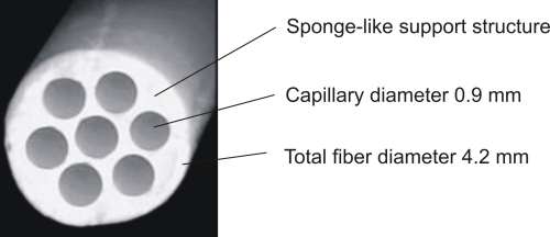
inge’s dizzer modules are equipped with patented multiboreÒ UF hollow fibres operating in in-to-out mode. Multibore fibres are made from modified polyethersulphone with a high pH tolerance from 1-13 which allows efficient cleanings even under extreme conditions. The inner diameter of each individual capillary is 0.9 mm, which is larger than the common 0.7 – 0.8 mm size, which increases the suspended particles limit. They have a larger diameter which can reduce the pressure drop and produce an even flow distribution along the fibre. This in turn helps distribute contaminants more evenly on the membrane surface and increases the backwash efficiency. The nominal pore size of the membranes is 0.020 mm, which provides for an effective rejection of bacteria and viruses.
The multibore fibre combines seven capillaries into one fibre which results in an exceptionally high mechanical fibre strength. This can overcome the major problem facing UF hollow fibre technology, which is that there can be a rather large number of fibre breakages during operation. In municipal applications, fibre breaks have to be repaired immediately because of the bacteria and viruses that can enter the filtrate water. In industrial applications,the RO membranes will be fouled quicker and UF will not fulfil its capabilities. No no fibre breakages have been reported in more than six years of operation in hundreds of plants that use multibore fibres. The benefits for the plant and the enduser are:
- reduced maintenance and repair cost
- increased protection and performance of treatment steps downstream
- increased operating safety.
Hydrodynamically optimised module design
The internal design of the dizzer module has an annular gap instead of the conventional central core tube which is commonly used to collect the filtrate and for backwashing. This design improves backwash efficiency by providing an even flow distribution along the module cross section and ensuring that all fibres are backwashed with the same intensity.
During backwash, the water flows from the annular gap towards the middle of the module. On its way, the total backwash water flow is reduced because a part of the water enters the fibres for the actual backwash. Since the number of fibres also decreases towards the middle of the module, the backwash flux will remain at a similar level over the complete cross section of the module. This results in a more efficient cleaning and subsequently in higher permeability and less chemical consumption.
The modules are mounted vertically for proper de-aeration to avoid water hammers. This arrangement makes it easier to access each module in case of maintenance.
How the system works
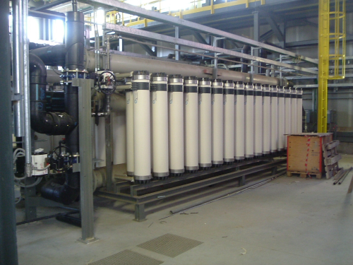
The UF system, designed for a total net output of 23,500 m³/d, consists of six trains, each equipped with 62 dizzer 5000 UF-modules. The modules are mounted in a vertical position with two rows of modules on either side of the central headers. The UF system was originally designed for five trains in operation plus one train on stand-by, but to avoid fouling in the stand-by train and to avoid increased wear from starting-up and shutting-down it was decided to operate all six trains permanently at lower than design flux. The design flux can still be reached if one train is shut-down for maintenance.
Each train is equipped with one feed pump which is controlled by a flow transmitter in the feed line for individual flow control. Next to the feed pump isa self cleaning filter with a nominal filtration rate of 300 micron. The purpose of the filter is to protect the UF fibres from potentially harmful objects – such as swarfs. For the backwash three 50% pumps are installed, and both feed and backwash pumps are equipped with a variable frequency controlled motor.
The UF process
UF is operated in dead end mode with a design flux of 79 l/m²h with five trains in operation. This figure originates from the tender, where a maximum net flux of 60 l/m²h with all trains in operation was specified. During filtration mode, the feed water enters the modules from either from top or from bottom, and the feed directions are swapped after each backwash. With these alternating flow directions. the total fibre length can be used more efficiently when compared to a design in which the feed water enters the module continuously from the same end. In this way, build-up of an irreversible fouling layer on the membrane surface can be avoided or delayed.
The operating philosophy of the UF system is to keep the transmembrane pressure (TMP), the main indicator of membrane fouling, at a continuously low level close to the initial 0.1 to 0.2 bar of a new module. In this way, irreversible fouling and extensive CIP cleanings can be avoided to a large extent. To clean the membranes a backwash is carried out every 45 minutes, and to control organic fouling, a chemical enhanced backwash using sodium hypochlorite with approximately 20 ppm residual chlorine and a soak time of 10 minutes takes place once a day. An additional chemical enhanced backwash using hydrochloric acid is carried out depending on membrane condition to remove any inorganic material carried over from the DAF.
For additional operational safety the plant is equipped with connections for optional inline coagulation upstream of the UF to further reduce organic material and improve the backwash efficiency. Currently no inline coagulation is applied.
Running (operating) a pilot plant
A containerised pilot plant with one dizzer 5000 module was set up after order award to demonstrate the functionality and operability of the modules and verify the operational data proposed in inge’s bid. The company also wanted to optimise its UF operating parameters for the large scale plant.
The pilot tests started in November 2006 and took four weeks. The water used, taken from the collecting basin for the cooling tower make-up water was actually worse than that conceived in the design basis, because it came from near the coast and from the surface. Construction work in the harbour basin had also caused increased turbidity levels. Since the power plant was shut down, water in the collecting basin was not running and had developed a poor microbiological quality. Upstream of the UF system, a small flotation system had been installed to which no coagulants were added. Considering all the above, therefore, it could be said that the UF feed water quality was significantly worse than that conceived of in the design.
During the first three days, the pilot plant operated at different fluxes of 60, 75, 90 and 100 l/m²h to get a feeling for how the plant worked with the given feed water. After this time, the flux was set to 80 l/m²h for the rest of the pilot period. The graph in Figure 6 provides an overview of the daily average main parameters during the complete pilot tests. The break in between the graphs was a shut down due to a power failure.
The pilot plant could be operated at a stable flux of 80 l/m²h. Regular backwashes were sufficient to fully recover the membrane permeability. The two daily chemical enhanced backwashes with sodium hypochlorite did not have any noticeable cleaning effect. However, in the long run the chlorine backwashes certainly enhance the cleaning efficiency and, therefore, are applied in the large scale plant as well. Only evaluation over a long term period will help to optimise plant operation.
Throughout the pilot period all SDI15 measurements showed values of below 2.
Installation of the full scale plant
Commissioning of the WTP started in June 2008, while the UF system started up at end of July and went on stream at beginning in the first week of August 2008. Because of the ongoing construction work at the power plant, there had been a reduced demand for process water and so only half of the WTP is now in operation. Currently, three out of six UF lines are operating and delivering purified water to two out of four RO lines. To prevent biological growth in the three UF lines not in operation, the racks are filled with water containing 0.1 % sodium bi-sulphite which is being replaced on regular intervals.
From start-up, the three operating UF lines have been run at design settings. Flux, filtration cycle time, backwashes and chemical enhanced backwashes are performed in accordance with the original design values.
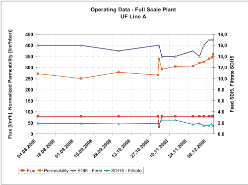
The graphs in Figure 1 showing the main operating parameters of UF line A since start-up are representative for the other two operating UF lines as well. The system has been continuously operated at a flux of 79 l/m²h with the exception of a short period where the capacity had to be reduced due to maintenance at the power plant. The transmembrane pressure stayed very stable at around 0.3 bar in spite of reduced water temperatures in the winter months – probably because of reduced biological activity causing less fouling. The normalised permeability has been very stable at around 250 l/m²hbar recently rising up to 360 l/m²h, with recovery higher than 93%.
Above operating parameters are particularly interesting against the background of an average SDI5 value of around 15 in the feed water which is beyond the design parameters. On the other hand, the filtrate water shows a continuously good water quality with an SDI15 below two almost all the time delivering excellent water quality to the reverse osmosis system. This very stable operation of the UF system could potentially lead to the extension of filtration cycles and reducing chemical consumption to reduce OPEX costs.
Since commissioning, the UF system has been operated under very stable conditions meeting all projected parameters in spite of challenging feed water quality.
Acknowledgements
The author gratefully acknowledges the support of Andrea Pagliari, Andrea Solito and Roberto Landi from Termomeccanica Ecologia in making available information and data of the plant.


