The performance of desalination plants is crucially dependent upon the design and performance of pre-treatment filters in removing solids. There are a number of different rapid gravity filter floor technologies that have been traditionally used in potable water treatment. This includes the TETRA® LP (Low Profile) Block filter floor system, which has been installed at more than 50 plants in locations worldwide since its development in the 1990’s. Contracts awarded in Europe to Severn Trent Services over recent years have been increasingly focused on pre-treatment for desalination plants, including Europe’s largest desalination plant, which is currently under construction in Spain. The dual parallel lateral design of the TETRA LP Block offers significant advantages for operators of desalination plants. The system’s robust plastic components are non corrosive, which is especially important in desalination plants, where salt in sea water causes corrosion. In addition, the nozzle-less design ensures there are no blockages that could potentially affect the performance of the filter. Existing filter designs The main components of a rapid gravity sand filter are the filter media, the gravel support layers and the filter underdrain. The underdrain serves to support the filter medium and gravel; to collect filtered water evenly from the bottom of the filter; and to distribute air and water evenly across the bottom of the filter during backwashing. Keys to these functions are the evenness of filtration and of the distribution of backwash air and water. The evenness of backwash water distribution is particularly important, as filter efficiency depends upon the effectiveness of the backwash cycle. The TETRA system’s two parallel laterals solve the problems of even distribution, common with other filter underdrain systems. The central (feeder) lateral has orifices along its length extending to a second parallel lateral called a compensating lateral. During backwash, water enters the central feeder lateral from a pipe or pressurised flume and is then distributed into the compensating lateral through orifices in this lateral. Variations in flow rate are evened out in the compensating lateral, enabling the system to provide an even distribution of backwash water across the entire filter bottom while minimising headloss.
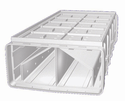
Practical application of this design uses preformed blocks made from high-density polyethylene which incorporate the feeder and compensating laterals within the blocks. The blocks interlock and are laid end to end in rows so that the laterals are aligned continuously across the entire filter. The rows of blocks are placed adjacent to one another across the entire width of the filter, and the blocks over the flume are anchored down with special anchor rods and the small space between the rows filled with grout. This has the effect of locking the blocks together to form a flat, level floor.
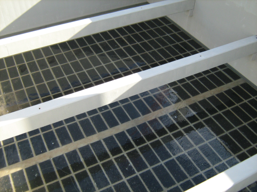
Gravel support layers prevent the fine filter medium from entering the underdrain and blocking it and help distribute the backwash water and air in the filter. Normally several layers of gravel are used. In the simplest form, the largest size gravel (about 20 mm) is at the bottom. Above this are layers of finer gravel down to 2 mm at the top. Each layer is about 50 mm thick, and total gravel depth may be up to 300 mm. Recently, media retention plates have been developed which are able to perform the functions of the gravel layers in a much smaller depth. As a result either the filter can be shallower or a greater depth of media can be used. The headloss across a media retention plate is the same as or less than for the gravel it replaces. Commercial Utilization The dual lateral underdrain was first developed in the United States in the 1970s. The LP Block design was developed in the late 1990s, featuring a single block measuring 412 mm wide by 225 mm high that is split into two channels. The block’s lower profile allows shallower filter or greater media depth. In addition, the block’s primary lateral area is larger than other blocks, so distribution is excellent at longer lengths up to 10m. The wider block requires less installation time and less grout between rows compared to other blocks, too, and can be adapted to retrofitting applications as well as new build. A new design A recent development in the market is the TETRA® FlumeFlow™, a system that works in tandem with the current TETRA LP Block design to offer savings in capital costs through the elimination of expensive fabricated air headers. Two recent contract awards for Severn Trent Services by ACCIONA Agua desalination plants in South America and North Africa will employ TETRA FlumeFlow technology. The desalination plants are due to be operational in mid 2009. The plant in South America will employ 4,428 TETRA LP blocks across 18 cells. The plant in North Africa will utilise 3,630 LP blocks across 20 cells. The TETRA FlumeFlow system’s design ensures simple construction of the central enclosed channel and eliminates the need for fabricated air headers within the cell. TETRA LP Block laterals give excellent distribution of backwash air and water along their length and the FlumeFlow™ design provides improved distribution between each lateral. Uniform distribution improves the efficiency of the filtration process through a more effective backwash when compared to other conventional filter floors. The TETRA FlumeFlow design accommodates the same flow regimes as the traditional LP Block design: filtration, air scour, water only backwash and combined air scour and water backwash The FlumeFlow has the following components: FlumeFlow interface plate; TETRA LP Block system; sealant; air L-pipe; and grout. FlumeFlow™ system overview A FlumeFlow interface plate is designed to fit into the LP Block and is sealed to provide an air / water seal and to prevent loss through the end of the lateral. It is fitted to the end of each LP Block lateral. The FlumeFlow is installed onto the lateral prior to fitting it into the cell. Each row of laterals is positioned to coincide with apertures that pass through into the enclosed chamber. The lateral is pushed into a grout bed and is fixed in place using the unique grout grip technology employed by TETRA LP Blocks. The new FlumeFlow™ interface plate has similar grout grips to the LP Block to firmly anchor the system in place. The smooth edge of the FlumeFlow interface plate is then sealed against the wall to create an air and water seal, which does not affect the integrity of the grout and hence maintains the high adhesion to the floor and subsequent strength of the floor. The FlumeFlow interface plate is then grouted into position to ensure that it does not move and maintains the seal. The grout is angled above the plate as this helps ensure that the whole filter is used with no dead space. The FlumeFlow design removes the need for a separate air header and utilises Air L-Pipes to control air to the upper chamber of the interface plate from the enclosed channel. Operation of the FlumeFlow A baffle within the FlumeFlow interface plate creates two chambers within it; an air chamber and a water chamber. It provides sufficient stability and velocity to ensure even distribution into each LP Block lateral for effective backwashing. During filtration, water collected in the LP Block laterals passes through the slot and water chamber to the enclosed channel where the output from each lateral is collected, combined and taken away. If an air scour is required at the start of the backwash cycle, air is pumped into the top of the enclosed chamber, forcing the water in it through the slots until the top of the L-Pipes is exposed to the air. After purging the water out of these air pipes, the air passes through the L-Pipes and into the different laterals, giving an even air scour. For a water-only backwash, the air is stopped (if applied), and the water is started, which raises the level in the enclosed channel again, forcing water through the slots in the FlumeFlow interface plate and into the laterals. With a combined air and water backwash, the air is not stopped, but the water started. The level again rises until the pressure between the air and the water balances. Air continues through the L-Pipes and into the top chamber in the FlumeFlow interface plate while water passes through the slots in the lower chamber. This balanced pressure is the key to providing a good distribution between the laterals and the FlumeFlow interface plate creates this even pressure.

