The selection of the size, number and type of flotation cells for a particular duty depends on two important factors. These are the required flotation residence time and the physical constraints of how much concentrate can be recovered for a given froth surface area and concentrate lip length. The residence time is influenced by ore type and characteristics such as liberation, kinetics and reagent dosage. Looking at the amount of concentrate that can be recovered, it also depends on ore type and additional characteristics such as particle size, specific gravity and mineral grade.
A combination of laboratory-scale test work and design scale-up factors will determine residence time. However, the froth carry rate (dry tonnes of concentrate per square metre of froth surface area per hour, t/m2/hr) and froth lip loading (dry tonnes of concentrate per metre of froth lip per hour, t/m/hr) cannot be determined in a laboratory. This is because the froth is scraped during a laboratory flotation test and thus does not exhibit natural behaviour, and it is not possible to scale-up froth transport distance. These values are generally compared via calculation to given maximum values to establish if these maximum values will be exceeded by the cell selection.
Cell selection — what matters?
So which of these parameters is most important for cell selection? If the residence time is met with a certain cell selection but the froth carry rate or froth lip loading are exceeded, what are the options? One option would be to increase the number of flotation cells to increase the froth surface area or concentrate lip length. However, this requires not only significant additional capital outlay, but also increased footprint and operating costs.
The important thing is to seek advice from those who know flotation intimately, namely your flotation supplier. They can provide potentially easier and more cost-effective solutions. Here, another option would be to customise the launder configuration to a larger froth surface area or lip length, without increasing the number of cells. Outotec has designed different launder configurations for its TankCells® and each launder configuration has a different concentrate lip length and froth surface area, providing customised designs for each individual duty and site. So-called ‘standard’ solutions may seem the quickest, easiest and least expensive, however a quick consultation can very often deliver simple, relatively inexpensive solutions to customise your launder (even on retrofits). This can improve recovery and provide savings in operational costs in the process. Having the correct amount of froth crowding will minimise the air requirement leading to capital and power savings.
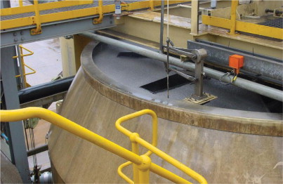
Central donut launder
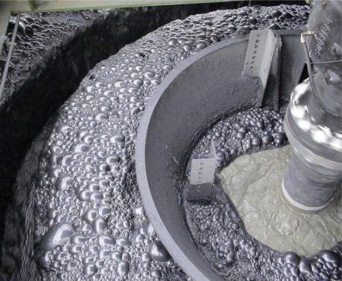
In a central donut launder the froth flows into both sides of the launder. The froth on one side is pushed to the launder by the froth crowder, with the froth on the other side pushed to the launder by tapered tank walls at the top of the cell. The launder is designed for optimum froth surface area on both sides. The launder is simple in design, inexpensive to install and well proven in industry.
Internal launders
The internal peripheral launder is a single launder located on the inside of the cell. Here, the froth is pushed to the launder by the froth crowder and also provides a simple and inexpensive froth transport solution.
With the internal double launder, the tank walls, froth crowder and one half of a donut launder crowd the froth. With this design, the froth flows into the launders in the same direction. This is particularly effective on high-grade ores that require high mass pull, hence additional lip length, with many retrofitted sites reporting significant improvement.
External launders
The external peripheral launder is a single launder located on the outside of the cell. As with the internal peripheral launder the froth is pushed to the launder by the froth crowder. This design, however, provides more froth surface area. The external peripheral launder does not consume cell volume, so the effective cell volume for flotation is also higher. This launder is predominantly used on smaller TankCells.
The external double launder includes a second internal launder, providing added concentrate lip length. This launder design is well proven in ultrafine and high mass pull applications.
Radial launders
In the case where a significant amount of lip length is required, for example in high concentrate mass recovery applications such as iron ore processing, radial launders can be added to the internal or external peripheral launder designs. A number of radial launders can be installed, depending on the cell size, and can also be retrofitted to existing installations to increase concentrate lip length.
Conclusion
The selection of flotation cells can depend on residence time, froth carry rate and concentrate lip loading. In order to minimise capital and operating costs, there are different launder configurations available, depending on the froth carry rate and concentrate lip loading requirements. Different sections of the circuit, such as the roughers, scavengers or cleaners, can each have different launder configurations to match the processing needs of the circuit.


