
Few components in plant and equipment engineering are as steeped in tradition as the pump. But how does this fit in with the age of digitalisation? This article explores the possibility of designing a hydraulic element which is fit for Industry 4.0.
Conditions can change during the life of a pump and it often happens that a pump no longer runs at the optimum operating point. This also applies to newly installed pumps. For years now, KSB experts have been looking to optimize pumps more easily without using complex analytics or having to replace the pump.
Digitalization offers tremendous potential for this. However, it takes time to develop new approaches and put them into practice. “It’s a matter of transferring decades of experience and expertise into an algorithm and a software solution,” explains Dr Thomas Paulus, Head of Programme Office Digitalisation & Startup Projects at KSB. “This cannot be done in a single step: It involves many different components and aspects. By bringing together these component parts, however, you end up with an intelligent and practical concept that provides real added value for the pump operator.” Step 1: Digital monitoring unit
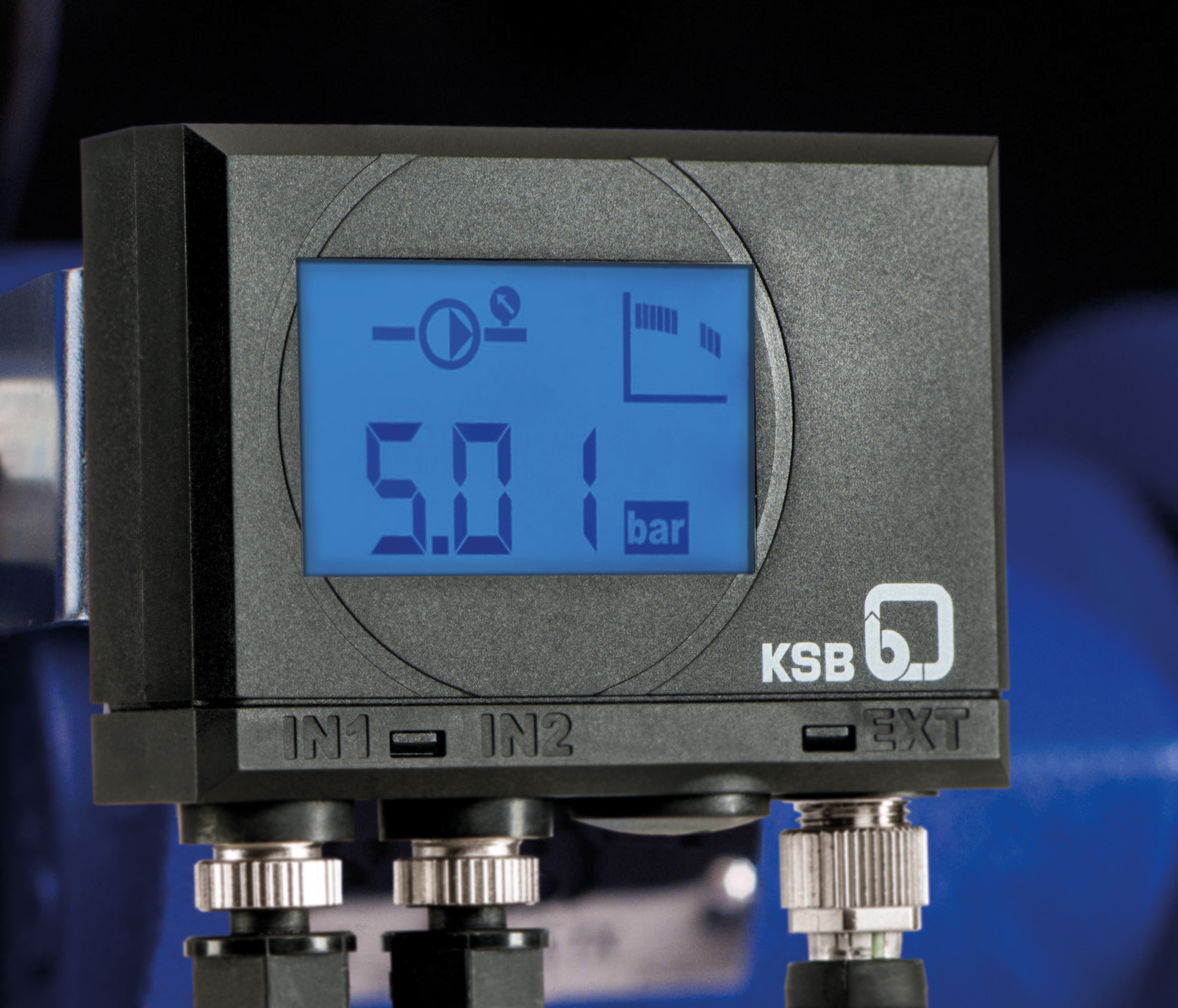
The company‘s “PumpMeter” monitoring unit, seen in Figure 1, shows what goes on inside a pump. The monitoring unit includes pressure sensors as well as an analysing and display unit fitted to the pump. Two sensors in the pump measure the suction and discharge pressures around the clock. The PumpMeter uses this data to calculate the differential pressure and determines the current operating point, which is updated continuously in real time. A typical four-quadrant pump characteristic curve shows the range in which the pump is operating at a point in time. A flashing outer segment on the left or right of the display indicates that action is required, either because the flow rate is extremely low or too high. A flashing third quadrant in the pump curve indicates the optimum operating range. If the segment on the left (the second segment) is flashing, this indicates a long-term need for optimization. This display allows the operator to evaluate the operating point immediately upon start-up and adjust the pump accordingly. Operators can see at a glance whether the availability of their pumps is at risk and whether they are operating economically. A flashing EFF (energy efficiency) symbol also indicates potential for significant energy savings.
Step 2: Vibration characteristics algorithms
This analysis now needs to be simplified further. In the future, instead of using wetted sensors, it will be possible to record vibrations and transfer this operating data to the cloud using mobile communication. This has two advantages: Firstly, conventional measurements using wetted sensors are not always straightforward, particularly when the medium being pumped is a chemical product. Secondly, cloud access means that technicians can obtain information about the status of a pump from anywhere in the world without having to be on site.
This application is currently being piloted with 100 selected project partners. Measurements taken in parallel using the PumpMeter are being used to verify the values obtained using the vibration sensor. At the same time, the company is continuing to optimize the underlying algorithms. According to Dr Paulus: “Based on these results, it is already easy to see whether it makes sense to switch to closed-loop control, whether the settings or modes of operation need to be changed, or whether it would be better to buy a new pump.” The operating data is transferred to the cloud via a portal. The company processes the data and the user receives an automatically generated PDF with clear recommendations and, where applicable, improvement suggestions for the pump (see Figure 2).
Step 3: Point optimization with MyFlow
But how can these improvement suggestions be put into action? The traditional approach would be to call a company technician. But what if it were possible, based on the information obtained, to adjust the pump using software instead of having to adjust the impeller manually?
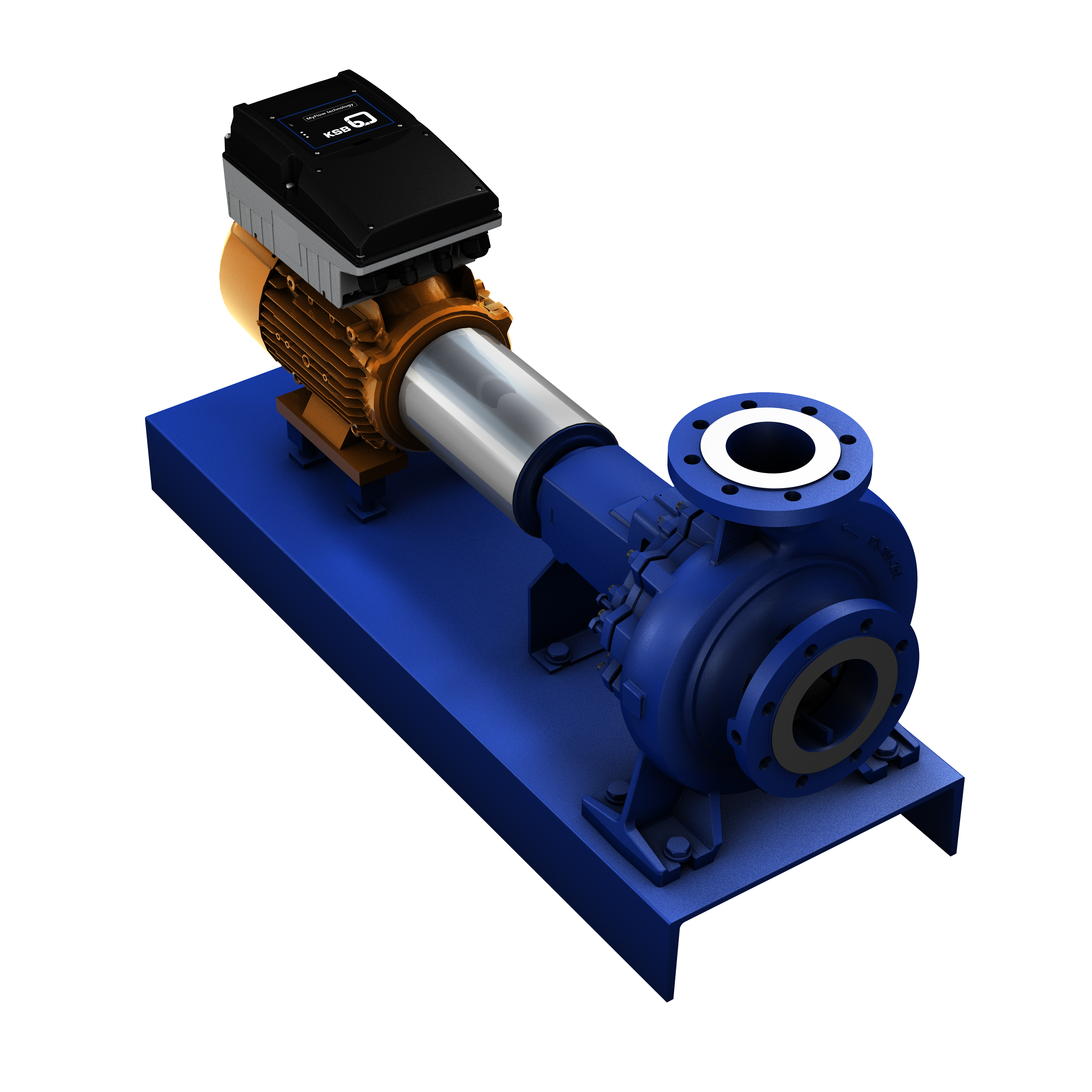
Figure 3 shows a combination of the company SuPremE IE5 motor and the MyFlow Drive, which is based on the proven PumpDrive speed-control system. The conventional approach for fixed speed pumps is to match the flow rate and head to the calculated operating point by trimming the impeller. Now, the pump can be adjusted by changing the speed.
MyFlow Technology could offer advantages in day-to-day work. Because the operating voltage of the IE5 synchronous reluctance motor is modulated by the minimum frequency inverter mounted on the motor, it can be used in almost any power grid. This could be an advantage for global engineering contractors because they may no longer need to consider the local mains voltage when selecting pumps. The direction of rotation is now defined at the factory, saving the time and costs usually incurred by conventional direction-of-rotation checks.
Step 4: Software-controlled pump adjustment
“Although these advantages make the pump operator’s job much easier, they are not enough to make a pump fit for Industry 4.0,” acknowledges Daniel Gontermann, Head of Product Management - Drives and Mechatronic Solutions at KSB. “Nevertheless, they form the basis for the next crucial step: pump optimization using virtual impeller trimming.”
In the further course of the product life cycle, the pump speed can be adjusted to individual requirements by smartphone; pump optimization with virtual impeller trimming. “A software application can be used to bring the pump closer to its optimum operating point,” says the pump specialist. Unlike with mechanical impeller trimming, the operating process does not need to be interrupted. This is how you can increase energy efficiency if the actual Q/H point deviates from the design values, or respond to a system-induced change in the operating point. “Because a change in speed is always associated with a change in power, substantial savings can also be made,” says Daniel Gontermann. Pump optimization through virtual impeller trimming is fast and convenient by smartphone or tablet via a Bluetooth gateway.
This is another aspect that is likely to play a major role in pump selection in the future. With individual fixed speed adjustment, fewer pump sizes now cover the entire selection chart, with efficiency and NPSH values remaining practically constant. The variant complexity for hydraulics is reduced by more than 50%, saving time and money on design and administration. “Simply reducing the complexity by having fewer variants will promote the topic of virtual impeller trimming,” says Daniel Gontermann.


