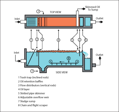
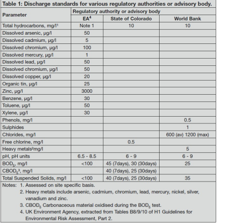
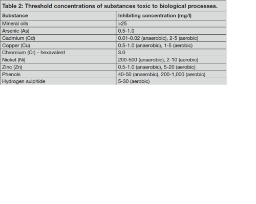
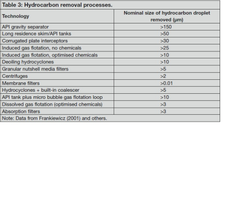
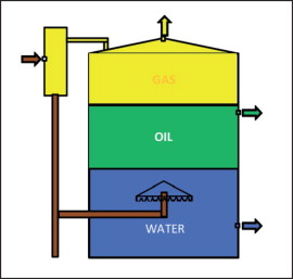
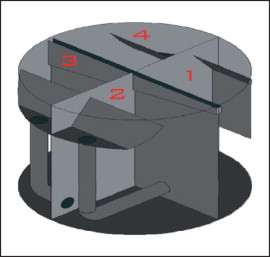
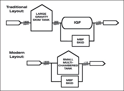
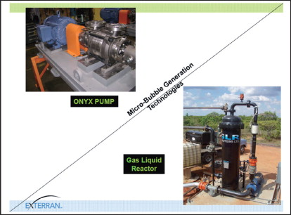
In the first part of this series of articles [1] treatment methods were reviewed for the discharge of produced water from offshore oil and gas production facilities. This article will review the situations where produced and other oil and gas field-derived waters need to be treated for disposal/discharge from onshore operated facilities and will focus on technologies used to treat produced and other waters emanating from onshore oil production systems. It will also touch on treatment options for the ‘infamous’ frac waters returned to the surface with gas as a by-product of the recent developments of gas associated with shale gas, as well as addressing some of the issues associated with treating to a suitable standard waters derived from the production of coal bed methane. The third article in the series will then deal with: • Discharge to near shore areas, and; • Injection, or re-injection, into subsurface rock formations. In addition to the produced waters associated with the production of oil and gas, water discharges from oil terminals and refineries, for example, will also need treating for either disposal or discharge to surface waters. The treatment of waters from refineries is outside the scope of this article. Some regulatory bodies, both national and state, mandate that wherever possible produced waters be treated and re-injected either for reservoir pressure maintenance or for disposal. Where this is not possible then rigorous discharge standards are applied. Some examples of these standards are set out in Table 1. Whereas the main focus for waters discharged offshore has until recently focused on its hydrocarbon content, where waters are discharged onshore there are many more parameters to be taken into consideration. Firstly, all of the bodies listed in Table 1 state that the main disposal alternatives may include; injection into the reservoir to enhance oil recovery and failing this injection into a dedicated disposal well drilled to a suitable receiving subsurface geological formation. Produced water discharges to surface waters or to land should be the last option considered and only if there is no other option available. The one significant area where onshore treatment facilities score heavily over offshore is in the availability of real estate so the need for high technology compact units is not normally a driver in process selection. In addition to waters produced during oil and gas field development water separated at oil terminals - a mixture of produced water separated in crude oil storage tanks and other process waters - is included in this discussion. An excellent guide for treating these waters has been generated by the European Commission in its Best Available Technology Reference Documents (BREF) [2, 3]. These give an overview of the types of water to be treated and methods which will allow them to be treated to achieve the required discharge standards. Of necessity they are very ‘broad brush’ and for the duties under discussion some selection of optimum processes will be needed. As the discharges onshore include the need to reduce 5-day Biological Oxygen Demand (BOD5), heavy metals and suspended solids, in addition to oil and grease, the process sequence must be such that any components which could adversely affect other processes needs to be removed initially. For biological oxidation processes (both anaerobic and aerobic) the substances in Table 2 are considered to be toxic to activated sludge processes [3]. As can be seen in Table 2 mineral oils need to be removed upstream of any biological process. Similarly several heavy metals not only exhibit toxicity towards biological processes; they also need to be removed to comply with statutory legislation. Thus any process scheme needs to remove these components upstream of any biological treatment stage. Where streams containing heavy metals can be segregated then these streams should be treated to remove these before commingling with other effluent streams. Methods that can be used to remove these components [3] include; • Precipitation; • Crystallisation; • Ion exchange; and • Nanofiltration. These technologies are well understood by the filtration and separation industry so will not be discussed here. Secondly, any mineral oil will need removing upstream of biological treatment and typical processes are discussed in Reference 3 and further data on their performance is given in Table 3. With space being available then large units, having long residence times such as the API separator, long residence skim tanks, i.e. gun barrel or API compartmented tanks can be used. These three units all separate not only hydrocarbons but can also be designed to remove any settleable solids in the influent stream and are illustrated in Figures 1 to 3. The API separator was developed by the Rex Chain Belt Company (now Siemens Water). The first API separator was installed in 1933 at the Atlantic Refining Company (ARCO) refinery in Philadelphia. Since that time, a significant proportion of oil terminals and refineries worldwide have installed API separators in their wastewater treatment plants. The API separator is a gravity-based device designed using Stokes Law. Based on this, most of the suspended solids will settle to the bottom of the separator as a sediment layer, the oil will rise to top of the separator, and the wastewater will be the middle layer. Any settled gross solids and trash need periodic removal from the trash screen in the inlet chamber. Typically, the oil layer is skimmed off and subsequently re-processed or disposed of, and the bottom sediment layer is removed by a chain and flight scraper (or similar device) into a sump for removal by a sludge pump. The water layer is frequently sent for further treatment consisting usually of a dissolved air flotation (DAF) unit for further removal of any residual oil and then to some type of biological treatment unit for removal of undesirable dissolved chemical compounds. Skim tanks and gun barrel tanks, for example, are normally designed to provide long residence times during which coalescence and gravity separation can occur. Skim tanks can be used as atmospheric tanks, pressure vessels, and surge tanks ahead of other produced water treating equipment. Their design can include a simple tank with water inlet/outlet baffles and oil skimmer; or the gun barrel type of tank where the produced oil, water, gas and any solids from the well or wells first flows into a degassing chamber. Gas flows up and is equalised with the gas phase in the tank. It commingles with gas evolving from the crude and is piped off to sales, flare, or a vent stack. Liquids flow down into the tank, and exit under a cone or spreader. The spreader typically has a serrated bottom made up of inverted V-shaped notches like saw teeth. The V-notches were included to ‘meter’ or distribute the flow of oil uniformly through the water phase, ‘washing’ the water out of the crude. API tanks are frequently vertical cylindrical tanks split into four compartments with the oil/water mix flowing sequentially through each compartment in turn. The water flow through each section is vertically downwards, with an internal tube connecting the bottom of each section to the inlet of the next section. The inlet system comprises an inclined baffle to distribute the water flow evenly upwards before it is diverted downwards where the underside of the baffle also acts as a surface to allow droplet coalescence. Any hydrocarbon separated in the individual compartments is collected in a common launder. Of late the compartmented API tanks have been upgraded to include a gas flotation loop (see Figure 4). The design consists of either a two or four compartmented API or similar tank with typically a six hour hold-up volume. The chambers are sequentially interconnected with a fresh stream of small (<50µm) gas micro-bubbles delivered to each chamber. Collectively these units should be able to remove high levels of dispersed hydrocarbons, even during periods of upset or high inlet oil concentrations. This micro-bubble system could be integrated into both new and existing skim tanks. In addition to the effects of the dissolved gas bubbles in reducing levels of dispersed hydrocarbons, another benefit to this design is that the tank is divided into separate chambers. This has been shown to reduce short-circuiting inside the vessel significantly. This novel design for an API tank combines the advantage of classic skim tanks, with surge and upset capacity and the efficiency of conventional micro-bubble flotation units. There are many different techniques available for generating small gas bubbles in aqueous streams. Those used in the generation of the micro-bubbles for the gas flotation tank discussed are shown in Figure 5. As shown in Table 3, the significant improvement in performance of the API tank when married to a gas flotation loop makes this an interesting option for the effective one-stage removal of the dispersed hydrocarbons from the water. Conventional wisdom [3] is that the API separator be followed by a buffer tank and a dissolved gas flotation unit. All three of these units can give rise to emissions to the atmosphere of any benzene, toluene, ethyl benzene and xylenes (BTEX) present in the water, all of which pose health hazards. The compartmented API tank plus flotation loop, being an enclosed system, does not generate atmospheric emissions, usually being connected to the LP flare. After any toxic substances and dispersed hydrocarbons have been removed, the oxidisable organic matter in the water can be addressed. A typical aerobic treatment system is capable of removing ~95% of the influent BOD and also ~95% of Chemical Oxygen Demand (COD) of the water [3]. So with a final BOD5 target of, say, 25 mg/l then the maximum BOD value in the influent would be of the order of 500mg/l. If the influent BOD is in excess of this then an initial stage of anaerobic treatment would be needed. These units are typically capable of removing 75% [3] of the BOD/COD from the influent so the maximum BOD/COD in the influent to a first stage aerobic process would be of the order of 2,500mg/l. Where higher influent levels of BOD/COD are experienced, then an additional stage of anaerobic or aerobic treatment would be needed. If it is assumed that the levels of BOD/COD in the influent fall within the 2.500 to 500mg/l range, then a two-stage biological treatment system will be needed. General practice for two-stage biological systems is to use an initial anaerobic stage followed by an aerobic stage of treatment, with final filtration of the effluent often being carried out.
Read Oil and gas: Treatment and discharge of produced waters onshore (Part 2)


