Aluminium is an extraordinarily versatile and economically important material. Although it is abundant within our planet's crust, the Earth does not want to give-up this silver-coloured, light, strong and corrosion-resistant metal easily. While its ore (bauxite) is relatively easily extracted, usually with surface mining, the process of refining the metal requires a great deal of effort. It is estimated that aluminium production accounts for around 1% of man-made greenhouse gas emissions. However, these are somewhat offset by the reduction in greenhouse gases emitted from cars, lorries and trains made from aluminium rather than steel [www.world-aluminium.org/About+Aluminium/Story+of].
The normal production route taken is to refine the bauxite to aluminium oxide, or alumina [Al2O3], which is a white, crystalline powder. This powder is then smelted to form aluminium metal. As a general rule, four tonnes of dried bauxite is required to produce two tonnes of alumina, which in turn provides one tonne of primary aluminium metal. While there are other applications for alumina, for example as an abrasive or in ceramics, the vast majority of global alumina production goes on to be converted to metallic aluminium. While the smelters tend to be located close to where the aluminium is needed, alumina plants are usually closer to the source of bauxite, or en-route to the aluminium smelter. It should also be noted that large quantities of fuel and sodium hydroxide are also required and their location and transportation costs are also factors in deciding the location of alumina plants.
The production of alumina from bauxite is a hugely significant industry in its own right but it is also one of the most significant global users of filtration and separation technology. A typical alumina plant may use approximately 500–1000m2 of filtration area per million tonnes of production (as well as many hundreds of square metres of gravity thickener/clarifier area).
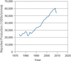
Production of alumina has approximately doubled in the last 20 years to more than 80 million tonnes. A significant proportion of this increase came from squeezing more capacity out of existing plants, or adding additional streams to these plants. The most significant producers of alumina are Australia, China and Brazil (see Table 1).
| Africa | 527 |
| North America | 7,148 |
| Latin America | 15,896 |
| Asia | 6,388 |
| Western Europe | 6,858 |
| Eastern/Central Europe | 5,569 |
| Oceania | 20,267 |
| China | 19,456 |
| Total | 82,109 |
The Bayer process
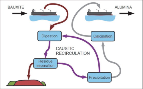
Almost all alumina plants in the world use the Bayer process, patented over 120 years ago [US Patent 515,895 Process of making alumina, Karl Bayer], to refine bauxite to alumina. In this process, a large volume of caustic liquor circulates continuously around the plant. Bauxite is fed into the caustic stream and, after a number of processes, alumina is taken out of the stream. The main process steps include:
1) Dissolution of the aluminium-bearing minerals using caustic liquor at high temperature and pressure.
2) Removal of the solid residue – the non-aluminium-bearing part is usually a mixture of iron-rich minerals.
3) Precipitation of pure alumina hydroxide [Al(OH)3], under conditions of controlled cooling.
4) Calcination of the alumina hydroxide to remove the water of crystallisation so that it is ready for the aluminium smelter.
This is a process that uses a concentrated caustic liquor at high temperature and which produces an extremely abrasive product – not ideal for filtration equipment. Indeed, filtration equipment in alumina plants face some of the harshest conditions found anywhere in the process industry.
A further interesting aspect of this process is that it depends upon each of the basic motivations for solid-liquid filtration types:
• separating valuable liquids from less valuable solids (residue separation).
• separating valuable solids from less valuable liquids (final product filtration).
• separating valuable solids from valuable liquids (seed filtration).
As with all production processes, there are four ways to look at success – the cost of production, the quality of the final product, productivity and safety, health and the environment (SHE). For an alumina producer, some of the more important considerations are:
Cost
• Efficient use of heat, caustic, capital employed and water.
Product quality
• Removal of non aluminium compounds (for example, the presence of iron or titanium compounds adversely affect the aluminium production).
• Consistent alumina particle size distribution; particles that are too fine will cause dusting, too coarse and they will disrupt the electrolytic smelting process.
Productivity
• Minimising product losses to the environment and waste.
• Operating 24/7 for as many days per year as possible.
Safety, health and environment
• Managing the risks associated with caustic – very high temperature and pressure.
• Managing the large quantity of residue produced.
Now we will look at some of the most important solid-liquid filtration processes, with reference to the four dimensions of processing success specified. There are, in fact a number of other possible solid-liquid filtration processes, as well as many solid-gas separation steps. However, the four steps of interest in this article are:
1) Residue separation – Red mud filtration
2) Residue separation – Liquor polishing
3) Precipitation seed filtration
4) Product washing and filtration.
The control head
The control-head, or rotary valve, is the critical piece of technology on each of the vacuum filters discussed in this article – pan, disc and drum. It provides the moving seal that contains the vacuum and pressurised air (for blow back and cake discharge).
In effect it is a switchable pipe manifold, with a fixed side, segmented into regions. Rotating against this are the pipe connections from each of the panels on the filter so that each panel experiences vacuum, ‘dead space’ or blow-back in turn, depending upon its point in the rotational cycle.
The environment of an alumina plant presents particular difficulties for keeping this component lubricated – grease and caustic are not a good match, particularly given the presence of an excellent abrasive.
Residue separation
The main aims in this step of the process are:
• to produce a clarified solution that can be delivered to the precipitation process.
• to produce a residual mud, containing a minimal amount of process liquor, that can be safely stored, or disposed of, by stacking.
This clarification is normally achieved through gravity settling clarifiers, with a final polishing filtration step for the overflow from the final clarifier and washing and filtration for the underflow (the red mud). Red mud disposal areas at alumina plants are unmistakable. The areas south-east of St Petersburg in Russia and around Perth in Western Australia are good examples of this.
Given the composition of bauxite, for every tonne of alumina produced there is approximately another tonne of red mud. Naturally, there is a certain advantage to refining alumina close to the bauxite mining activity, since the red mud can be used to back-fill the mine. However, it is important that the quantity of caustic in the mud is minimised and that the disposal area is sealed to prevent leaching of caustic soda into the surrounding soil.
Filtration in the process – red mud
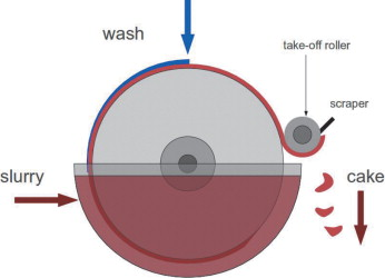
In most circumstances, plants use vacuum filters, usually drum filters, for the final washing and de-liquoring of red mud before it is sent to a waste area. In this process, the solids are waste and the liquor valuable. The reasons for using drum filters are their reliability and ability to discharge thin, sticky cakes.
The feed to the filters at this stage may have a solids content of around 40% wt/wt and the liquor contains a quantity of caustic soda and dissolved aluminium. The drum, with panels covered with cloth and under vacuum, rotates in an agitated trough containing the underflow from the last gravity decanter/washer. As it passes through the trough, a cake forms on the cloth, typically this cake will be less than 5mm thick. As the cake emerges from the trough, it enters a zone flooded with hot wash water, fed through a wash-bar at the top of the drum (although some filters may use a spray system). Finally, after continuing through a drying zone, where liquor is drained from the cake, the mud reaches a discharge system (often using a roller to peel the cake away from the cloth.)
The capacity of the filter is determined by the applied de-watering force and the rate at which filtrate can pass through the filter cake (the filterability) and through the filter itself (the equipment hydraulic capacity). Increasing the rotational speed will increase the throughput. However, it should be remembered that the theoretical capacity is, at best, proportional to the square root of the rotational speed (so doubling the speed would give an increase in throughput of around 40%, but a significant potential increase in component wear – see The effect of rotational speed). It is also necessary to check the liquor capacity of the filtrate system of your filter and associated tanks and piping in the installation.
A further incentive to reduce the speed is the increased residence time of the mud in the wash zone. Borges and Aldi reported that ‘a rotation of 1.4 rpm resulted in an average caustic concentration of 17.7g/L, against 23.6g/L when operating with 3.1 rpm’. [Using a Statistical Model in the Red Mud Filtration to Predict the Caustic Concentration in the Red Mud Borges A. and Aldi J. Alunorte Light Metals 2009, pp. 117–119]
The effect of rotational speed
The capacity of a trough-feed rotary vacuum filter is a bit less than proportional to the square root of the speed. So, doubling the speed (×2), with all other things being equal would give a capacity increase of around the square root of 2 -1.41. So the best possible increase would be around 1.4 times the old capacity – a 40% increase.
Of course, if capacity is limited then there may be no choice, and the filters would need to run as quickly as needed to reach the capacity. However, if there are ten filters, but by running five at their maximum achievable speed the required capacity can be reached, what would be a sensible operational regime?
Given the relationship between speed and capacity, it is possible to tabulate the scenarios for capacity. Given that the filter cloth is at its most vulnerable when the cake is pealed from it by the discharge roller (or discharged by blow-back air) and the cloth enters the trough to be hit by fresh slurry, we could suppose that the cloth wear is proportional to the number of cake discharges. So the lifetime will be the inverse of this. It is also likely that the wear on some other parts on the filters (for example, the control head) increases sharply with speed as they approach their design limits. For example, think about a car running along the motorway in top gear at 2,500 rpm and another running at the same road speed in second gear at 5,500 rpm. In addition, in a highly caustic environment stress corrosion could be an issue so reducing the stress on filter components that are in the slurry is a good idea.
The following table gives the approximate rotational speed required. Interestingly, if seven filters are operated (just two more), the required speed is around half of that for the original scenario of five filters. Also, the total number of filter rotations reduces sharply, with a reduction of nearly 30% with seven filters.
| Number of filters | Required speed (rpm) | Total number of rotations per minute (number of filters multiplied by rpm) |
| 5 | 5 | 25 |
| 6 | 3.5 | 20.8 |
| 7 | 2.6 | 17.9 |
| 8 | 2 | 15.6 |
| 9 | 1.5 | 13.9 |
| 10 | 1.3 | 12.5 |
This is not to say that the optimum will be to run all ten filters at 1.3 rpm. Other issues need to be considered. For example, will the cake thickness increase above its best point for cake discharge? In addition, what will happen to the overall vacuum pump capacity and power consumption?
A suggestion would be to run one of the filters at a slower rate and monitor its performance (throughput, washing result and cake discharge), spares (particularly cloth) and power consumption closely in order to optimise the installation.
Future trends
There have been numerous attempts to find uses for red mud. Karl Bayer's original patent suggests that the red mud residue could be used in the production of iron. However, so far, there have been very few successes in this endeavour. Currently, there are some initiatives to pursue the idea of exploiting red mud as a construction material for example (see www.redmud.org). Some of these applications would depend upon complete removal of caustic and other liquors from the mud.
In some cases, filtration technologies other than vacuum drum filters may also be used, for example filter-presses at Aluminium of Greece's Saint Nicolas Plant and at Alcan's Gardanne plant in France. However, there is not yet a sign of a significant migration to this technology.
Bokela GmbH has suggested that its Hi-Bar continuous pressure filter could be used for red mud filtration, which would give the advantage of reducing caustic losses and producing a mud with a higher solids content.
Filtration in the process – liquor polishing
The accumulated overflows from gravity settling may still contain a small amount of fine suspended solid matter. If these particles are allowed to pass into the precipitation process, they would contaminate the product with, for example, iron and titanium compounds. This will then affect the properties of the alumina and, ultimately, affect the aluminium smelters. For this reason, the liquor is passed through polishing filters to remove this matter.
Generally speaking, the most common type of filter used for security filtration is the vertical-leaf pressure-filter – Kelly filters.
A rough guide for sizing leaf filters is to assume a flux rate of approximately 1 m3m−2h−1 (1 cubic metre of liquor per square meter of cloth per hour). Of all the filtration applications in alumina, security filtration appears to be getting the most attention from equipment suppliers at present. The industry is constantly looking for automatic, reliable and self-cleaning equipment for this application. Many filters installed in this application require a great deal of attention. This is mainly because of scaling (precipitation onto the internal surfaces and of, and media within, the filters).
Precipitation seed filtration
During Karl Bayer's original development work, he mixed a dose of aluminium hydroxide crystals into the sodium aluminate solution to provide a seed for precipitation. This technique is still used today, on a scale several orders of magnitude greater than the glassware used in St Petersburg during the 1880s.
In the modern interpretation of the Bayer Process, vast tanks are used to give the pregnant-liquor a long residence time in the presence of seed particles and under carefully controlled cooling, so that the solution can give up its product to the solid phase. On a particularly cold day, especially when it is also windy and rainy, the productivity of a Bayer Process precipitation circuit can increase significantly. However, this may also introduce a disruption in the control of the particle size distribution. In another largely exploited precipitation process, the manufacture of precipitated calcium carbonate (PCC), the time required for the crystals to form is almost zero. In the case of alumina, several tens of hours can be required in order to produce the carefully controlled particle size distribution required by the process of making metallic aluminium.
Once the liquor has given up all of the product that it can (and therefore become spent-liquor), it is separated from the solid product (usually in large settling tanks) and returned to the beginning of the Bayer circuit where it is re-heated and re-concentrated, ready to meet fresh incoming bauxite. The solid particles at the end of the precipitation chain are classified, with those meeting the required product size being diverted to the calcination step and those under-size being returned to the top of the precipitation chain to act as a seed for precipitation.
There is an advantage to stripping out the spent-liquor from the slurry of seed that passes back up the precipitation chain in order to maintain a high concentration (and therefore more precipitation potential). This gives the plant a productivity boost.
Filtration in the process
The seed slurry in this application filters under vacuum in a few seconds to produce a very substantial cake, in some cases, more than 50 mm. In most cases, vacuum filtration is used for this application, occasionally, drum- or, more typically, disc-filters.
This is not a challenging filtration process in terms of the difficulty of the separation itself, but rather in terms of handling very large throughputs of heavy, abrasive cake in a highly caustic mother liquor. A further challenge is handling very large quantities of filtrate, in other words, the filtrate system on the filter itself and throughout the installation must be well designed.
Filter cloths
All of the filter types in this article normally use woven filter cloths made from polymer yarns as the filter medium. Normally polyamide (nylon) or polypropylene are used. If you are not sure what a piece of cloth is, a soaked piece of polypropylene will float in water while a soaked piece of nylon will slowly sink. The cloths operate in severe conditions in terms of temperature, pH and abrasion. Nylon has a reputation for being particularly suited to high temperature, abrasive applications, while polypropylene is normally thought to be suitable for high pH slurries.
Hydrate filtration and washing
The graded and classified solid product from precipitation must be washed in order to remove the process liquor which would contaminate the final product and interfere with the smelting process. The aims here are to:
• Produce a filter cake that is dry enough to be fed to the calciner.
• Wash the cake free of process liquor.
Filtration in the process
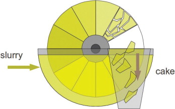
Most commonly, pan filters are used for this application. They are used because of their relative compactness and cake-washing capabilities. Pan filters resemble disc filters, but with the discs arranged horizontally. In this case, the throughput of the filter is determined entirely by the quantity of slurry delivered to the filter, independent of the speed of the filter. Slurry is poured onto the filter pan (which is under vacuum) and, as the pan rotates, it is washed and air drawn through the cake in order to displace liquor. The filter-cake is typically removed using a screw, set just clear of the filter cloth, to convey it sideways from the pan and into a discharge chute. Finally, the cloth may be given a back-pulse of compressed air to keep it clean. Cake moistures are typically well below 10% by weight. In reality, the cake moisture is not strongly sensitive to the rotational speed. It is necessary to make the choice between a thin cake with air flowing through it for a short period or a thicker cake with air flowing through for longer.
In practice, the filter rotational speed is set to ensure that the filter-cake is thick enough for adequate discharge. Some operators prefer to run the filters as fast as mechanically possible, with a thin cake. However, running at a slower speed can give some benefits in terms of filter cloth lifetime and washing results (increasing the residence time).
Conclusion
Alumina is a vital step towards production of metallic aluminium. The Bayer process requires a great deal of filtration capacity yet presents enormously challenging conditions for filtration equipment.
The filter equipment and filter cloth suppliers have responded, and continue to do so, producing robust filtration products.


