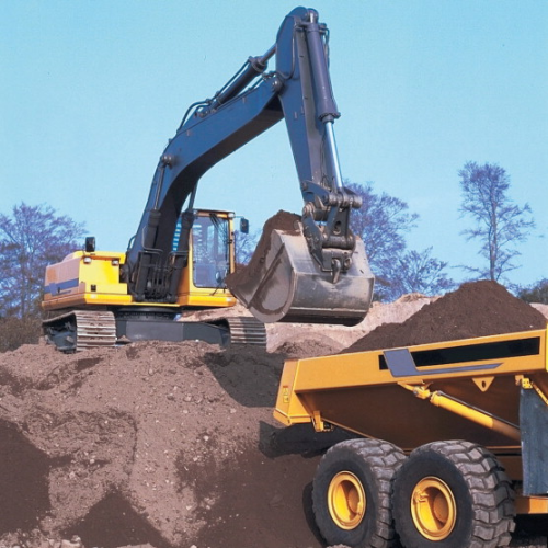

Today's manufacturing environments place great strain on production machinery. In the drive to maximise productivity, quality and throughput, users demand equipment that can generate ever larger forces with ever more precision. The elimination of process steps in sheet metal production, for example, calls for larger press tools and, in turn, more powerful presses. In mining and construction, higher equipment capacity is essential to minimise the time and labour costs in earth and spoil moving operations. Tighter tolerances and the desire to minimise or eliminate secondary finishing operations, meanwhile, require equipment that can operate with extreme precision.
Commercial demands serve to compound these challenges. Operators want machines that will operate faster to reduce part cycle times. They also want to maximise the overall availability of equipment, by running production lines for longer, by implementing rapid, automated changeovers between parts and by extending the intervals between maintenance interventions. Above all, they do not want unplanned downtime caused by equipment failure. With many operations involving multiple items of equipment, economic production requires every piece to run at extremely high levels of reliability.
Hydraulic technology remains a supremely effective way of generating large forces at acceptable speeds, using proven equipment that operates with high reliability under demanding conditions. Nevertheless, hydraulic technology can in some applications have certain important vulnerabilities. For example, during operation and maintenance, hydraulic fluid can pick up contamination in the form of dirt, water and wear particles. Over time, this contamination can cause severe damage to seals, pumps, cylinders, valves and other components, degrading performance and ultimately leading to catastrophic failure. Such failures are not only expensive to fix, they also have the potential to disrupt production cycles. In many modern production environments, the combination of extended operating periods and fast cycle times serves to increase the risk of hydraulic fluid contamination and damage, with industry estimates that over 85% of all hydraulic system failures can be attributed to fluid contamination.
The sensitivity of hydraulic equipment to contamination comes, in part, from the extremely fine tolerances used in its manufacture, where clearances of between 0.5 and 5.0 microns are common in parts such as pumps and motors. Particles too small to be visible to the naked eye are quite capable of causing damage to these components. In fact most damage creating contaminants are less than 14 microns in diameter: around the size of a human blood cell. Contaminants have a variety of damage mechanisms. Abrasive wear damages precisely machined surfaces as particles are dragged across them. Particles in high velocity oil can also erode component edges and surfaces. By obstructing the film of lubricant oil between surfaces, contaminant particles can also permit metal to metal contact, creating adhesive wear, in which surfaces weld together, then break apart as components move. Trapped particles also create surface cracks, ultimately causing fatigue failure in components.
Keeping contaminants out of hydraulic systems is however, almost impossible. Even before a system is first commissioned, it will contain many millions of particles left over from its own manufacture, assembly and transportation. The new, fresh hydraulic fluid used to fill the system may also contain significant quantities of contaminants. Once operation begins, contaminants can accumulate in working hydraulic systems at a surprising rate. Even in cleanroom environments, particles will enter a typical hydraulic system at a rate of around one million per minute. In an indoor manufacturing environment, contamination will accumulate ten to one hundred times faster. While outdoors in a dirty construction or mining environment, millions or more particles may enter the system every minute.
In addition to solid particulates, water dissolved or entrained in hydraulic fluid can also cause significant damage, through corrosion and by destroying the additives used in the fluid to protect components and extend its service life. Relatively small concentrations of water have been shown to reduce the life of components dramatically. Increasing water contamination levels from 100 parts per million to 250 parts per million, for example, will halve the life of a bearing.
Typically, manufacturers of hydraulic equipment specify the required cleanliness level for oil in systems using the ISO4406:1999 Standard. This scheme estimates contamination by counting the number of particles larger than 4, 6 and 14 μm in a 100ml sample of fluid.
In practice, it is impossible to assess hydraulic fluid contamination by visual inspection. Although high levels of contamination can result in cloudiness, or in visible particulates within the fluid, most damage will be caused by particulates that are too small to be seen by the naked eye. At elevated temperatures, such as those typical of hard working industrial applications, fluid can absorb significant quantities of water while remaining visually clear.
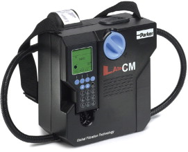
Within the field of fluid system maintenance the Portable Particle Counter continues to be an important instrument. Developed to allow on site, rapid identification of the levels of particulates in systems, this is now the accepted way of monitoring levels of solids in fluid systems. Capable of accurately and repeatedly reporting levels of particulates down to 4 μm (c) in size, they are also lightweight, portable and reliable.
With a test taking typically two minutes, laser particle counters offer portable counts and cleanliness codes. In taking a fluid sample from a system, however, care must be taken to make sure that the sample is representative of the system. ISO 4021 (1992) is the accepted standard for extracting fluid samples from an operating hydraulic fluid system and must be followed at all times. In the standard approach, the system should have been at operating temperature for at least 30 minutes before the sample is taken, sampling valves should be opened and flushed for at least 15 seconds, and the clean sample bottle should be kept sealed until the fluid and valve are ready for sampling.
In some cases, for example when there is reason to suspect water contamination, or when the viscosity of the system fluid requires analysis, samples should be sent to a certified laboratory. Laboratory spectrometric analysis can also indicate the condition of the additives within the fluid and identify the nature of metal particulates, which can be useful in diagnosing the sources of contaminants caused by internal wear.
Filtration extends equipment life
The best way to eliminate damage from contaminated hydraulic fluid is the installation of inline filtration systems to capture particles before they reach sensitive components. The design and specification of such systems does, however, require considerable care. By impeding fluid flow, filters reduce the efficiency of a hydraulic circuit. If they are not properly designed or sized, pressure loss across filters can significantly reduce the efficiency of hydraulic systems, increasing energy consumption and the associated challenges of heat management. At worst, poor filter selection will actually impede overall system performance, reducing operating speed and affecting product quality.
As well as machine performance, correct filter selection must allow for overall operating conditions. By their nature, filters will require periodic cleaning and replacement to ensure efficient operation of equipment. Filter packages should be sized to ensure that the required frequency of intervention matches that of the overall equipment maintenance strategy in order to minimise the cost and disruption associated with filter care.
The leading designers and manufacturers of filtration systems for industrial hydraulic machinery are constantly refining the design of their equipment in order to maximise performance and minimise the associated drawbacks. In the remainder of this article, we will examine some of those refinements and their effect on filtration system performance and reliability.
Filter design
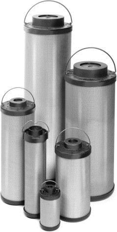
Many aspects of filtration system design affect the pressure drop across the filter. The first of these is the filter material itself. Filter material, made of glass fibre, is available in a wide range of different grades. Those that capture smaller particles will impede flow more than a filter grade with a more open structure. Overall pressure drop in the system is determined by the type and grade of material used and the area of material available. A larger filter of a given material will offer less resistance to flow, but will of course be more costly to purchase and may be difficult to install in the optimum location in a system. In mobile hydraulic equipment, the size and location of the filter can be particularly critical, since space on the vehicle can be extremely limited, and designers must balance protection of the filter equipment from damage in service with ease of access for maintenance.
Different filter materials also have different dirt holding capacity. This capacity — the amount of material of a given size that the filter can hold — helps to determine its service life. To extend the life of a filtration system, manufacturers like Parker use multiple layers of different filter materials to ensure that larger particles do not prematurely overwhelm the finest filter materials in the system. These layered and laminated designs also help to minimise the potential for media migration, where shards of glass fibre material from the filter can break off and find their way into the downstream oil flow.
Recent advances in filter materials modify the composition and construction of standard glass fibre materials to improve their strength and dirt holding capacity while also reducing resistance to flow. Parker's Microglass III material, for example, can reduce dynamic pressure across the filter by 8% while improving contamination loading by 15% typically, compared with conventional filter material.
The material and finish of filter flow surfaces are also critical. Parker filters typically use a spheroidal graphite cast iron (SGI) material at the filter head and a cold drawn steel bowl: each material selected to allow the right combination of strength, manufacturability and good surface finish. Likewise, extreme precision in manufacture and assembly is required to ensure that the desired flow characteristics are achieved in production.
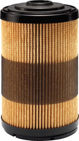
To accommodate a larger area of filter material into the filter body, a pleated design is used. The precise design and stiffness of these pleats affects filter performance. Where the pleat is folded, the fibres in the filter material are compressed, which can restrict oil flow. To minimise this effect, Parker filters use a larger U-shaped pleat fold instead of the conventional hard V-shaped crease. As each individual pleat is slightly larger using this approach, the exact design is selected to be a careful compromise between the number of folds in the filter material, and the packing of the pleats in the filter body in order to achieve the desired level of flow restriction. Pleats need to flex a little in use in order to absorb energy from the oil flow, particularly in press tool applications with significant transient pressure changes. Too much flex, however, will reduce the dirt holding capability of the material.
Filter selection considerations
When selecting a hydraulic oil filtration solution for manufacturing or construction applications, plant managers or maintenance personnel may find it instructive to take a lifecycle cost perspective. The overall cost of filter installation includes the purchase and delivery costs of the original system and of replacement filter elements. It also includes the cost of waste oil during filter changes and the increased energy costs of running the equipment due to losses in the system.
Some of these characteristics can change significantly over the life of the filter. For example, while two different filter materials may exhibit similar pressure loss characteristics when new, the accumulation of particles during operation may result in a much more rapid increase in losses in one material, together with increasing energy consumption and early element replacement.
Where water contamination is an important issue, absorption elements can be installed. These units contain a desiccant material, which captures entrained water as the oil passes over it. Water that is fully dissolved in the oil, however, can only be removed using a separate vacuum dehydration system.
Specification decisions can have an important impact on lifecycle costs. For example, doubling the size of a filter element will reduce energy losses significantly and will extend the life of the filter element by a factor of three, thanks to the increased dirt holding capacity of the additional material. Of course, doing this will increase the initial purchase costs and the overall footprint requirements of the filter installation.
As operators continue to demand more from their hydraulic equipment, attention to monitoring, maintenance and protection will become increasingly important. Skilled maintenance personnel and a rigorous and appropriate maintenance strategy will minimise the chance of unexpected failures, and the right filtration solution should form an intrinsic part of that strategy.


