Non-graded wound filters are popular in the filtration industry, but filter efficiency is crucial. In this study, the filtration efficiency of graded and non-graded wound filters was found to be different. This indicates that performance seems to be affected by the change in winding pattern that is done during build-up.
Introduction The use of polypropylene spun yarn for producing wound filter cartridges is well known. These candle filters have their own merits and demerits. They rely on the thickness of their medium to trap the particles. When they are in use, the particles tend to enter inside the filter matrix, which can cause them to be arrested. Also, the pore size of these filters may not be uniform, implying that they can trap a wide range of particles. They also have a greater ability to withstand pressure. However they tend to discharge trapped particles back into the filtrate under the influence of pressure.
Manufacturing (winding) technique To manufacture a wound filter cartridge, a filter winder is used to wind the feed material (polypropylene spun yarn), in a particular manner on a perforated core, up to a pre-arranged thickness. Winding is a science that has a crucial role to play in the performance of wound filters; however is still an unexplored area.
This paper will try to highlight some aspects of winding to produce a wound graded filter cartridge. There are certain terms that frequent winding science which need to be defined for the benefit of readers like wind, traverse ratio etc. The number of coils (coil number) laid on the package in single traverse is known as wind (wind ratio) whereas the number of coils laid on the package in a double traverse is known as traverse ratio.
Single traverse means, for example, yarn movement from the left to the right side of the package and double traverse would be the yarn movement starting from left and returning back to the starting side. The angle formed by the direction in which the yarn is laid and any plane perpendicular to the package axis is known as coil angle (θ); inversely related to the wind/traverse ratio.
Observation of the wound filters can be helpful in determining the traverse ratio. For example, if one counts the yarn crossing points along the package axis, for example, 8.5, this means that approximately 8.5 coils will be laid on the package as the yarn moves from one side of the package to the opposite side. However, yarn crossing will be visible only when the coils cross each other and that would happen because of the traverse reversal. So, as the yarn is moved in the opposite direction, the coils will cross the previously laid coils and in doing so, lay another 8.5 coils. Thus the total number of coils in double traverse or traverse ratio will become 17 (8.5 + 8.5); double the wind ratio.
The wind ratio mentioned is 8.454 as was set on the filter winder and not 8.5, so its equivalent traverse ratio will be 16.908 (8.454 X 2); known as actual traverse ratio. The nearest whole number to 16.908 is 17; this is the nominal traverse ratio. Thus, nominal traverse ratios are numbers that have a small denominator (for example, 17/1, 35/2, 51/3…). Selecting a traverse ratio like 17 or any whole number for that matter can result in the problem of patterning which is observed when successive coils are laid exactly on top of previously laid coils, resulting in density variations. Here the coil comes to the same place after every double traverse. Thus the number in the denominator (1) indicates the number of double traverses after which the coil would come to the same starting place. A number slightly greater or smaller than the desired traverse ratio should be selected to obtain similar package characteristics but without pattern formation. However the actual traverse ratio can also be written in fraction form as 16908/1000. The number in the denominator here is large comparatively. So the actual traverse ratios are numbers having a large denominator. Thus, such packages will have characteristics close to a package with a traverse ratio of 17 but will not produce a patterned package. The difference between nominal and actual traverse ratio or vice versa is known as gain. It gives an idea about the precise displacement of a coil after every pattern repeat which is one in this case, as the nominal traverse ratio is 17 (17/1).
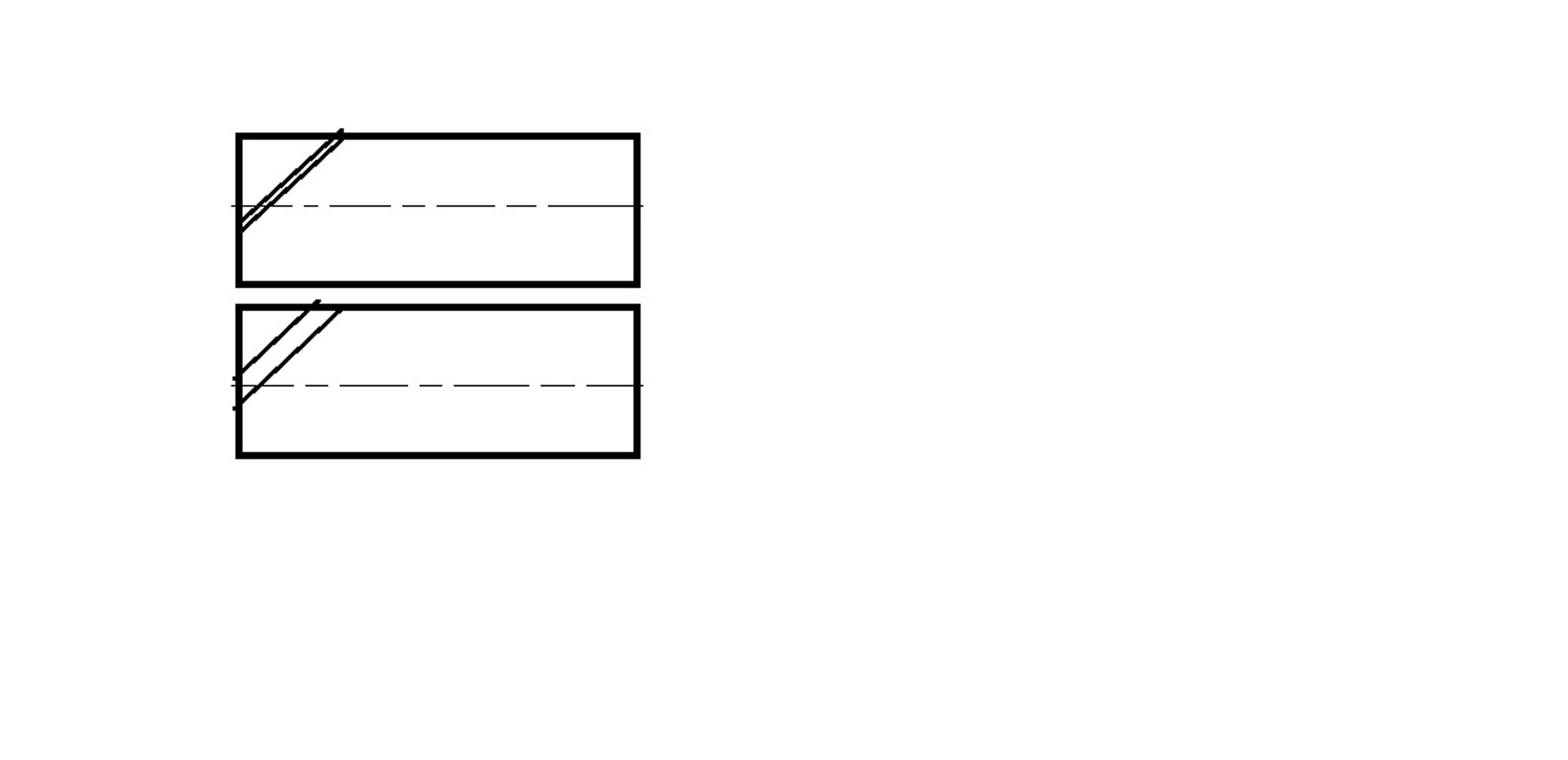
In the above example, gain comes out to be 0.092 and is expressed in terms of revolution/pattern repeat. This means that after every double traverse the coil gets a precise angular displacement of 0.092 rotations. Increasing the gain will increase the angular spacing between the coils as shown in Figure 1, which will result in a package with open wind. Changing the gain is found to have an influence on the density of wound packages. A package with more density would indirectly mean more resisting surfaces, resulting in greater amount of opposition to the fluid flow as well as the suspended particles present.
Wound graded filters Winding of string filters is done on filter winder that is different from that used for winding regular yarn. Commercial winders are grouped into three categories: random, precision and step precision winders. Cross wound packages produced on random winders are not preferable for applications that deal with fluid flow as it may show density variations during its build up, due to pattern formation. The package produced on precision or step precision is preferred for the said application.
In the case of the precision winding system, the traverse ratio is constant, hence the selection of actual traverse ratios near their whole nominal traverse ratios are set, for example, (17/1), half (17½), one third (17⅓ or 17⅔), one quarter (17¼ or 17¾), which prevents patterning. A wound cartridge can be called ‘graded’ only if density variation from the core to the surface is observed, which is not possible in the case of cartridges produced on mechanically operated precision winding machines.
The step precision winding machines are able to produce packages with a constant coil angle without pattern formation. Thus, packages are quite stable and uniform in density; suitable for fluid flow applications. Mechanically controlled step precision winders are costlier compared to the mechanically controlled precision winder.
Nowadays, electronically controlled systems are available in the market for regular yarns that can selectively be operated on precision/step precision principles as required. In this work, wound filter cartridges have been produced on an indigenous electronically controlled winding system for winding 10 in filter cartridges in the precision winding mode.
Three wound cartridges were produced for this study: one with close wind (CW), another with open wind (OW) and the third was combination wind, resulting in a density graded cartridge (G). The close coil spacing/close wind was selected at the beginning (on the core/tube) as is denoted by CW and when the package diameter reached almost half the intended value, the coil spacing was automatically changed to a lay yarn at greater angular spacing that resulted in open wind package as is denoted by OW.
Performance of graded filters The performance of wound filters is based on pressure characteristics and the difference in particle count in downstream and upstream fluid. The test time for the wound cartridges was two hours on an apparatus designed as per ASTM 795-88. The test was set with constant flow rate conditions wherein the concentration of slurry was 0.1 g/L. The pressure drop which was recorded after 120 minutes with OW, CW and G was (6.792, 7.574 and 7.345) psi respectively. It can be expected that open wind would offer lower resistance to fluid flow, but amongst the close wind and graded, the graded filter is showing a lower pressure drop. Therefore, with similar winding conditions, the change in pressure drop is an indication of improvement, owing to the changes made during the buildup.
Figure 2 shows that the particle size distribution of filtrate samples for CW and G match almost exactly. However, the retention of smaller particles in the case of the OW wound cartridges is poor, but for the rest of the particle sizes, it is better than CW and G. The same graph also shows the pressure drop experienced by each of the cartridges, which is highest for CW and lowest for G. The most important thing that one has to remember is that in the given experimental set, only the angular position between the coils was changed. When the cartridges were wound so that the coils were touching each other, the pressure drop was greater.
However, when the cartridge was produced with coil spacing (almost twice the yarn diameter), the pressure drop experienced by it was less. This implies that though none of the winding parameters other than the coil spacing was changed, pressure characteristics changed. When G cartridges were produced, they experienced lower pressure drops than the CW which could be seen as advantageous. Finally, the nominal rating of the wound cartridges was found to be 81 μm for OW, 69 μm for CW and 56 μm for G when the water samples were observed under a microscope.
Conclusion The electronically controlled winding system enabled the manufacture of wound graded cartridges. In this study the coil spacing was altered during build-up to obtain wound graded cartridges. The comparative performance analysis of wound cartridge samples reveal that graded cartridges can give lower pressure drops compared to their counterpart along with better micron ratings. Thus, manufacturing sectors should take this information and launch graded cartridges to attain better field results.
References Please contact the author directly for full references.
Contact Dr. Pragnya S. Kanade Textile Engineering Department, Faculty of Technology and Engineering, The Maharaja Sayajirao University of Baroda, Vadodara, Pin: 390001 Gujarat, INDIA Email: p.s.kanade-ted@msubaroda.ac.i
Co-author Mr. Tejas Desai


