Those industries that use compressed air for production purposes will always benefit from pure compressed air. These industries range from heavy engineering and spray painting to the hi-tech pharmaceutical and semiconductor sectors.
For the compressed air filtration industry, progress is usually achieved only in small steps. Engineers are rarely given a blank sheet of paper and told to embark on radical improvement, using what they have learnt over the last generation or so. But this was the brief for the engineers involved in developing Parker domnickhunter's latest filtration equipment. Looking to address critical areas, such as air flow management, filtration media selection and construction, and the efficient removal of coalesced liquid, the company's engineering team set about developing a technology which would combat these areas and also be compliant with the international standard ISO8573.1, the air quality standard which details the method for filter testing.
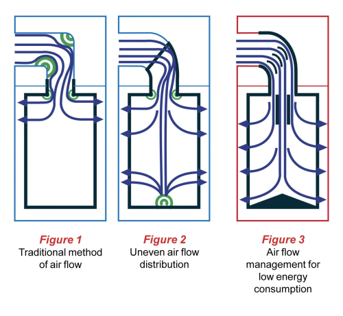
Air flow management for low energy consumption
The design of a compressed air filter housing is critical as it can directly affect system pressure losses, which in turn result in higher operating costs for the user. The pressure loss or pressure drop of a filter housing is a fixed ownership cost. Only through careful design, can this fixed cost be kept to an absolute minimum.
The inefficient corner
Due to installation restrictions and for ease of maintenance, compressed air filters are designed to be installed vertically at 90° to the piping system. This design restriction therefore requires the air stream to turn a corner and, in a typical compressed air filter, the air is turned sharply through 90°. In aerodynamic terms, this sharp turn is known as an inefficient corner. In a compressed air filter, an inefficient corner leads to turbulence, system pressure loss and high running costs (see image, figure 1).
So, what causes this turbulence? The core of the approaching air stream is projected against the outside wall of the turn. Part of the flow is reversed and a vortex pair produced, the remaining air continues downstream in a slightly more uniform manner. The vortex pair has the effect of narrowing the flow path through the corner, throttling the air flow and increasing pressure losses.
Making the inefficient corner efficient
To improve air flow and reduce turbulence, the sharp corner should be made rounded and smooth. The rounded corner produces a different type of flow as the air stream lines diverge near the outside wall of the turn and converge on the inside wall. Compressed air filters using this design offer improvements over those using a sharp corner to turn the air stream as turbulence induced pressure losses are reduced (see image, figure 2). However, it has been found that through the use of partitions (turning vanes) in the air flow, inefficient corners are greatly improved as they are separated into a number of more efficient corners (see image, figure 3).
Eliminating pressure losses
Looking to combat such problems, Parker domnickhunter designed the Oil-X Evolution filter range. This technology has been developed from the ground up with the key design focus concentrated in critical areas, such as air flow management, filtration media selection and construction, and the efficient removal of coalesced liquid. The range has also been designed to be fully compliant with the international standard ISO8573.1.
The filter range has been designed to eliminate all unnecessary pressure losses. As the air stream enters the housing, a ‘bell mouth’ inside the inlet port reduces the level of turbulent flow entering the vessel. The air stream then enters the full flow inlet conduit of the filter element top endcap where it is turned through 90° using a full radius blended bend. Turning vanes within the inlet conduit split the 90° corner into a number of smaller, more efficient corners. The air stream is therefore channelled, reducing turbulence and pressure losses.
Terminating the conduit directly after the 90° change in direction can cause additional areas of turbulence, resulting in increased energy consumption and uneven usage of the filter media. The filter element employs a flow distributor to ensure the air stream is evenly distributed throughout the filter element for maximum performance and energy efficiency. To prevent additional turbulence from air hitting the lower element endcap, a conical flow diffuser is employed to ensure smooth and efficient air flow.
Filtration performance and operational costs
Correct filtration media selection and construction is fundamental in achieving compressed air to the highest quality and also ensures system operating costs are kept to a minimum. The pressure loss (and thus the operating costs of a filter housing) is fixed; however the operating costs incurred from the filter element are incremental. A poorly selected filter media could not only result in contamination being carried downstream, but also a filter element which requires frequent maintenance and has a high cost of ownership.
Verified by Parker domnickhunter, and also independently confirmed by testing at Northumbria University, the Oil-X Evolution filter elements have been designed to provide air quality to international standards whilst keeping incremental operating costs to a minimum. Typical compressed air filters soak up oil and water and are said to run in a saturated state. The saturated media temporarily blocks the path of compressed air through the normally open filter structure and increases the pressure loss as the air flow has to force liquids through the fine matrix of the filtration media.
This pressure loss increases throughout the life of the element as the filter media becomes blocked with particulate and this directly relates to the operating cost of the filter. The filter elements have been designed to provide a very low initial saturated pressure loss which stays low throughout the 12 month guaranteed life of the element.
To achieve this, the filter media selected for use was a borosilcate glass nanofibre with 96% open area, or voids volume, providing an extremely high dirt holding capacity. A special oleophobic coating is also employed to actively repel oil and water, ensuring the open area is kept to a maximum for dirt entrapment. Additionally, the surface area of the cartridge has also been maximised by using ‘deep pleat’ media beds, this being a first for the industry. Deep pleating provides surface areas up to five times greater than filter elements using a standard wrapped construction. This allows the overall filter size to be reduced and ensures that the pressure loss of the filter starts low and stays low throughout its life.
High efficiency grade filter elements also use a graded density media pack. This consists of two grades of filter media within the pleat pack. A course pre-filter layer protects the fine layer from premature blockage, improves air flow and, therefore, helps keep the operating costs lower for longer.
Efficient removal of coalesced liquids
Once liquids are removed from the air flow, they must be prevented from being re-entrained back into the clean air and carried downstream. It can be said that a coalescing filter is only as good as its liquid drainage mechanisms.
The filters incorporate many design features to ensure that all coalesced liquids are effectively and efficiently removed. The anti re-entrainment systems incorporated into the filter range can provide high liquid removal properties, low pressure loss and temperature and chemical compatibility. Typically, the liquid coalesced by a filter forms a wet band around the bottom of the filter element from where it eventually drops into the filter bowl and is discharged by the drain. Because of this wet band, designers would usually incorporate a quiet zone into their filter housings to ensure that air does not flow through this area and cause re-entrainment.
In addition, the anti re-entrainment barrier employed by the filter elements not only ensures that liquid contaminants are rapidly removed before they can be carried downstream, but are also re-located under the filler element away from direct air flow. This eliminates the potential for re-entrainment. It has allowed the removal of the quiet zone, thus resulting in a more compact and lightweight product. Additional liquid removal is also provided by surface tension breakers in the lower element endcap and drainage ribs cast into the filter housing. The drainage ribs compress the anti re-entrainment barrier ensuring the speedy removal of the liquid through capillary action.
Installed in a compressed air system using an 185 kW compressor, the company says the technology could save the user up to 60% per filter in energy consumption compared with many other filters on the market.


